
Regulated B+
Regulated is what it sounds like. The voltage variation police watch over your B+ output and make sure it doesn’t change. This can be achieved with tubes or solid state devices. Although it’s often complicated and expensive due to the high voltage parts required, regulated B+ gives you a rock solid supply and predictable performance. This is especially useful when your amp draws varying amounts of current or if you’ve found that the voltage from your wall socket varies a lot throughout the day.
Unfortunately, as the amp gets larger and the voltage and current requirements get higher, regulated B+ quickly increases in complexity and cost. That said, it’s an interesting alternative for small amps and line level devices. You’ll often see sweet ass VR tubes in regulated supplies.

Boost Converter/SMPS
Switch Mode Power Supplies and/or Boost Converters are often found where size and weight are major design goals. These power supplies operate on a high frequency switch that, along with an inductor’s magnetic field, let you create a high DC voltage from a low one. You’ll frequently see them used as or with ‘wall wart’ power supplies.
SMPS’s and boost converters are poo-pooed by the audiophile crowd because of the potential for high frequency noise that they introduce and their inherent design complexity. If designed and implemented properly though, switching power supplies are just as useful as any other topology. Check out Pete Millett’s website for designs that use this flavor of power.
Voltage Multipliers
Voltage multipliers multiply voltage. You probably figured that out. Typically they are a fairly simple network of diodes and capacitors arranged to charge the capacitors to the AC peak voltage on both halves of the AC cycle. The full wave voltage doubler is especially useful for getting 300V from cheap and common isolation transformers:

But you don’t have to stop at doubling the voltage. Quadruplers, and sextuplers are also possible configurations for getting high B+ voltage from a low AC supply. Your raw DC voltage from these multipliers will be the original voltage times the multiplication factor time the square root of 2. For example, 120V AC from an isolation transformer fed through a doubler (x2), doesn’t give you 240V; it gives you 240V times the square root of 2. That’s about 330V, without factoring in the voltage lost to the drop across the diodes and filtering. Remember to respect high voltage and build your shit safe.
Multiple Voltages from a Single Winding
Voltage doubler circuits can also be combined with standard bridge rectifiers to get multiple voltage rails from a single transformer winding. These types of circuits can be a great cost and parts saver when you need more than one B+ value, provided you rate the transformer appropriately. Several variations of this idea exist for transformers with and without center taps.
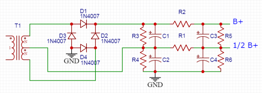
The “Millet Doubler” is detailed here and uses a single center-tapped winding. The entire secondary is rectified via a bridge rectifier, rather than the usual approach of grounding the CT and using a full-wave rectifier. The center tap voltage is then rectified and feeds the lower half of a stack of capacitors.
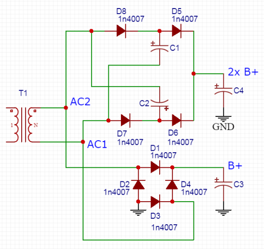
The “TubeLab Doubler” is something I found posted on diyaudio.com; it is also discussed in depth here. This one uses a single winding without a center-tap. The doubled voltage rail is somewhat lower than what you’d get in the Millet Doubler, but still potentially useful especially with inexpensive isolation transformers.

I can only find a schematic of the “TubeCAD Doubler” (no discussion), but if you’re familiar with TubeCAD’s blog, it doesn’t look too unfamiliar. See a good article on multiple power supply voltages here. This one looks a little bit like a combination of the other two variations.
The caps in these circuits can generally be rated for half of the high voltage rail level. The levels of voltage ripple will often vary between rails and some versions of this kind of circuit will produce a lower voltage ‘doubled’ rail, but the usual filtering methods can produce smooth DC voltages without trouble in all cases.
Choke Input
Chokes (inductors) don’t like quick changes in voltage. In a choke input power supply, we send the choppy DC voltage from the rectifier directly to the choke instead of a capacitor. This choke, and its magnetic field, calm that choppy voltage the f*%k down much better than (normal sized) capacitors can. The drawback to this approach is that, unlike a capacitor, the choke isn’t charged to the peak voltage; it’s charged to about 90% of the unrectified AC voltage (two times the square root of 2, divided by pi).
Sometimes the voltage decrease with choke input can be useful. If you are designing from scratch and buying all new parts (feck your big budget, btw), it is easy to compensate for. Additionally, adding a small cap (just a few uF) before the choke lets you tune the voltage output. Try playing with the size of the first cap in a CLC filter in PSUD2 to see how it affects the voltage output.
