

Pastafarian deity
The first time anyone sees a series regulated tube power supply, they start to question what they know about tubes. If it’s an especially tricky regulator with pentodes and stuff, they might question their ideas of audio altogether. And if there’s a zener voltage reference, watch out. The poor tube head will probably forsake their God-or-lack-thereof and move to the woods to ponder the meaning of power supplies, social structure, and self-actualization. To save you from this crisis of identity, we’re going to talk about tube regulation from the inside out.
Tubes really only care about two things: the voltage difference between their anode and cathode and the voltage difference between their grid and cathode. Usually with grounded cathode amplifiers we call the former “B+” and the latter “bias.” If we have a finite load, increasing the B+ with the bias held constant increases the current through the tube. When we increase bias with the B+ held constant, we decrease current through the tube.

If, on the other hand, we hold the current constant, we see that increasing the bias (making the grid more negative relative to the cathode) means more voltage is required between the anode and cathode. Decreasing the bias has the opposite effect. This changing voltage drop between anode and cathode is the basics of tube power regulation. We don’t make use of this dropped voltage in the power supply; we make use of what is left over. The trick is in telling the “pass tube” how much voltage it should be dropping.
Now, imagine a troll.
Yeah, like that. This troll watches the pass tube and determines how much voltage it gets by measuring what it sees and then telling the pass tube if it needs more or less. It tells the pass tube what to do by dragging the pass tube’s bias up or down.
If the troll wants to see a constant amount of voltage, despite changes in current, he just has to keep telling the pass tube to adjust. Of course the power supply voltage must always be higher than the voltage that the troll wants, usually by at least around 100V, so that the pass tube always has room to drop voltage and keep the output constant with varying current demands. Consider the following diagram depicting the pass tube, error correction troll, and his voltage reference.

“u wot m8 tree fidy ryt fookin volty droperoo”
But trolls aren’t real, are they? So what can take its place in an actual regulator application? If you said “a tube,” you are correct. Any tube can use its grid as a way to sense a voltage level and turn it into a signal (in this case it’s a signal for the pass tube). We call this sensing-and-signalling tube the error correction amplifier. The trick is giving it a way of comparing one voltage to another (remember that a tube only cares about the difference between cathode and grid). For that, we need something that has a very constant voltage drop, regardless of the amount of voltage or current in its supply.
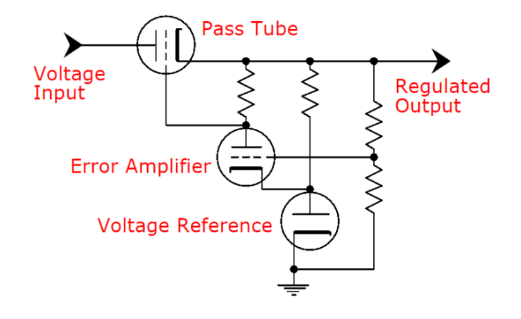 A VR tube or zener provides a nice constant and reliable voltage reference for the error tube. With the reference voltage at the cathode and a voltage divider feeding a portion of the output voltage to the grid, the error tube will amplify any difference between them. If the voltage is too high, the grid of the error amplifier becomes less negative relative to the cathode, causing it to conduct more current and increase the voltage drop across its load resistor. This pushes the pass tube’s grid more negative relative to the cathode, meaning a higher voltage drop across the pass tube and lower voltage output. If the output voltage is too low, it all happens in reverse and I’m too effing lazy to type that out.
A series pass regulator automatically corrects the output in order to keep the error amplifier (troll) happy. The error amplifier is only happy when the voltage reference (VR tube or zener diode) and the voltage it sees across the resistor voltage divider are equal. As long as the voltage reference is stable, the pass tube has lots of headroom, and the error amplifier has lots of gain, this leads to a very consistent and ripple-free voltage output.
