

Suggested reading before tackling this page: Impedance & Reactance, Grounded Cathode Amplifier, Output Transformers
“Having the amp for a couple days now, I can’t tell you how much I love this amp, it’s like listening to my music collection all over again, every song I’m treated to new surprises, The layers and soundstage in the music is amazing, The bass is fast and tight and the midrange is to die for, the highs are perfect, it was almost like this amp was meant for the Audeze headphones.” – Bob, Audeze LCD-2 owner
I’m sitting here asking myself what the shit I’m doing trying to DIY a headphone amp. Headphones are a pain the in the butt. For one thing, headphones from various manufacturers can have wildly different impedance ratings. Impedance is kind of a big deal when we’re figuring out how to not crap the proverbial sound quality bed. In addition, manufacturers seem to just provide whatever specs they feel like in whatever measurement standard strikes their fancy. Oh, you wanted milliwatt power ratings? Tough shit, cabrón, you get voltage. Sensitivity? What in the world would you want to know the sensitivity for? Just plug them in. You’ll like them, we promise.
But, headphones are a great way to enjoy your tunes when a pair of speakers just won’t do. Headphones are also affordable, resulting in a lot of folks building a collection of models for different moods, genres, and environments. Most headphones benefit from a quality amplifier. Sure you can listen right from your iPod. You can also plug your speakers into a cheap home theater receiver. There’s nothing wrong with that. But as a man in a nun’s habit once told me–in the alley behind the convenience store- “Variety is the spice of life. You’ll like it, I promise.”
So if we’re going to design and build a tube headphone amplifier that will work reasonably well with a variety of models, what should we consider?
- Damping factor
- Properly loading the tubes
- Sufficient listening levels
- Frequency Response
- Simplicity
Damping Factor
Damping factor is a measure of how well an amplifier controls a transducer (speaker or headphone driver). It is calculated by dividing the speaker or headphone’s impedance by the output impedance of the amplifier. A higher number generally equates to tighter bass. And who doesn’t love a tight bass? Due to their intrinsic plate resistance through, tubes generally have a high output impedance that we need to overcome to achieve a good damping factor. Luckily, there are a couple of common methods to lower the output impedance of a tube.
Cathode followers are able to achieve an output impedance of roughly 1/Gm. This has been used in many headphone amp designs to good effect. The de facto tube of choice for this kind of design has been the 6AS7. In a standard cathode follower configuration, the output impedance of this tube would be around 140 ohms. That gives us a damping factor of about 2 with 300 ohm headphones (not terrible), but with low impedance headphones the damping factor is way lower. For reference, the damping factor of a typical 300B amplifier playing through 8 ohm speakers is around 4 or 5.
The other approach for lowering output impedance is to use an output transformer. This is what you see in speaker amps that have to contend with 4 and 8 ohm loads. Headphone impedances are much higher than speaker impedances, which is good, but finding an output transformer with secondary taps for a large range of headphone impedances can be difficult. Luckily, headphones need very little power, so we have some leeway in selecting a transformer when it comes to reflected impedance.
Properly loading the tubes
For good distortion and power performance, we usually want our transformer to reflect an impedance of at least 3x the plate resistance of the tube. Our reflected impedance is the square of our transformer’s turns ratio multiplied by the load. For a lot of small tubes (ie the kind that would be most appropriate for headphone amps), this requires a high turns ratio if we want to use 32 ohms headphones. The same turns ratio would result in a pretty batshit high impedance with 300 ohm cans (limiting the output power), so we are going to want multiple secondary taps to keep everything within reason.
Pro audio matching transformers come in a lot of flavors for matching the output and input impedance of various studio gear. One of the common ones is 10k:150. Some of these 10k:150 transformers also have center taps on the primary and secondary, meaning we can get a 10k:37.5 impedance ratio as well. Edcor makes just such a sexy beast in WSM (½ watt) and XSM (2 ½ watt) sizes. Guess what I gots in my parts bin. The various configurations allow for about an 8k load with 32 ohms, a 20k load with 300 ohms, and everywhere in between with other headphones. That’ll do.
Sufficient listening levels
The chosen transformer has possible turns ratios of 16.3 or 8.2, depending on how we use the secondary. We are going to use the whole primary (for maximum inductance), so the ratios 8.2 and 16.3 represent the full secondary and half of the secondary respectively. The voltage that we create across the primary will be divided by this ratio when it appears at the secondary. A pair of Sennheiser HD600s are 300 ohms and produce 98db at 1 volt. To get this one volt on the 8.2:1 ratio tap, we need to apply 8.2 volts on the primary. Easy peasey, lemon squeezy. A pair of Grado GS1000e’s are 32 ohms and need 1 milliwatt to produce 99db. One milliwatt into 32 ohms is only .2 volts. To get this .2 volts on the 16.3:1 ratio tap, we need to apply only 3.2 volts to the primary.
To calculate the damping factor provided by the Edcors, we use the square of the turns ratio. Say we want a damping factor of at least 8 with 32 ohm headphones. The output impedance of the tube before the transformer should therefore be 32 ohms divided by eight, multiplied by 16.3 squared. That’s an output impedance of about 1,000 ohms. Using the 8.2 ratio tap for 300 ohm headphones with the same output impedance means a damping factor of about 20. Toight like a toiger bass.
Frequency response
Another morsel to stick in your brain stew is the bass extension of these little Edcors. Edcor specs the WSM 10k:150 as having a 19H primary inductance (most likely measured at 1khz). We know that the -3db point will be determined by:
f = Z / 2 * pi * L
The Z number above is the tube’s plate resistance in parallel with the reflected impedance (ie the output impedance if the cathode is bypassed). If we use a tube of about 1,000 ohms plate resistance and have a reflected impedance between 8,000 and 20,000 ohms, depending on load, Z will be 800-950 ohms. Factoring in the 19H as a baseline, we see that bass should not be rolled off until below 10hz. In practice, inductance generally increases at lower frequencies, too. Swing low, sweet chariot.
Simplicity…FFFUUUUUUUUUUU
Here’s where the universe tries to piss on our parade. The Edcor transformers do not have an air gap. This means that we cannot simply run DC through the primaries like we would in a single-ended speaker amp because we’d lose the inductance (and the bass). So, we’ll have to use a coupling cap to connect the transformer primary to the tube’s anode (AKA parafeed). The cap prevents DC from passing to the output transformer, but AC flows through just fine. Yay, more calculations! The -3db roll off point created by the cap will be determined by:
f = 1 / (2 * Pi * C * Z)
Where Z is the reflected impedance (8k ohms, see Properly Loading the Tubes) and C is the cap in farads. A cap of 4.7uf (which is affordable in film caps instead of icky electrolytics) gives us a roll off point just below 5hZ.
Because the capacitor is in series with the primary of the output transformer, and the primary of the output transformer has an inductance, we must also consider the reactance of the system (the frequency dependent portion of impedance). Ignoring ESR of the capacitor and DCR of the inductor, the total reactance is given by:
total reactance = 2 * Pi * f * L – 1 / (2 * Pi * f * C)
When this equals zero, we have a resonance. We don’t want a resonance in the audible frequencies:
resonance at f = 1 / (2 * Pi * L^.5 * C^.5)
A larger L and/or C helps to push resonance lower. This is the part of the design process where armpits start dripping, brains start exploding, and dry cleaning bills go through the roof. When the cost of dry cleaning exceeds the cost of parts, you just build the damn thing and see how it sounds.
We still need to figure out a way to send current through the tube, of course. The usual ways to do this are to use: a resistor (like a regular resistor loaded gain stage), a choke (like an output transformer without the output), or a CCS (constant current source). Whatever we put in the anode will look to the tube like it is in parallel with our parafeed output transformer, so ideally we want a super high AC impedance to prevent lowering the overall load impedance. Don’t worry, we’re getting to simplicity, I promise.
A huge resistor can create a big AC impedance, but it would mean we’d need a lot of B+ voltage. Scratch that. A choke creates frequency dependant impedance, so we’d want to make sure there is plenty of inductance to keep the tube loaded at low frequencies. Unfortunately, big inductance usually means big price tag. Finally, a CCS provides an uber high AC impedance at all frequencies that matter, but it often means multiple little solid state bits and a means of biasing them.
Enter the 10M45S current regulator from IXYS. This is a one chip, one resistor solution for our CCS. That is as simple as it gets. Also, they’re only a couple bucks a piece. Tits.
Choosing our tube
Using the information above, we know we want a plate resistance of around 1,000 ohms (or less) for our tube. Along with the Edcor WSM/XSM transformers, this should give us the damping factor and bass extension that we want and be properly loaded with multiple headphone impedances. Because headphones need puny power, we can look at smaller and cheaper tubes rather than the big power tubes we would use for speaker amps. As far as low output impedance small triodes, we have a few nice looking options:
- 12B4A – cheap NOS, Mu of 6.5, Rp of 1,030 ohms, 5.5W anode dissipation
- 6AH4GT – cheap-ish NOS, Mu of 8, Rp of 1,780, 7.5W anode dissipation
- 6S45PE – current production, Mu of 52, Rp of 1,150 ohms, 7.8W anode dissipation
- EC8020 – sell a kidney, Mu of 55, Rp of 900 ohms, 8W anode dissipation
There are approximately one metric butt-ton of other options, but using standard heater voltages and lower currents simplifies the power supply, and using tubes that are reasonably common means people can actually build this thing.
The 12B4A and 6AH4GT are both well-respected tubes, but the low Mu worries me a bit for this application. Taking into consideration the voltage ratio of the output transformer, both would need slightly over 1 volt input from the source to get to 98db on headphones like the Sennheiser HD600, even with a bypassed cathode. Portable players often don’t provide any more than 1V output (some even less) and home audio products rarely get over 2 volts. Should you actually listen at 98db? Hell no. But a little extra dynamic headroom and/or extra gain for quiet recordings is good to have. So these tubes might work fine, but they also might need an additional input tube to increase the voltage gain.
The EC8020 is about perfect for our use but they are unobtanium. On the other hand, the Russian 6S45PE tube is in current production from Sovtek/Electro Harmonix (and is available NOS), so it’s not hard to find. With similar Mu to the EC8020, the 6S45PE can easily hit 110db on something like the HD600s with only 0.5V input. The clincher is that it can be a single tube per channel solution AKA a ‘one tuber’ AKA spud AKA papa (en español).
Thus, it has been decided and we shall call thee Papa Rusa (Russian Potato).
The fun stuff
Design Highlights
- Switchable output transformer secondary for >100 ohms and
- 10M45S CCS provides about 30mA, putting the tube in an ideal operating region. This requires modest heatsinks (CCS dissipates approximately 4W at idle)
- Simple SS rectified power supply, CLC filtered, approx 275V of B+
- Operating point of 150V on the anode with a -1.5V bias (at 30 mA)
- Power output on 32 ohms headphones with 1V input is approximately 150mW. With 300 ohm headphones, power output is approximately 50mW. The amp is perfectly capable of forever ruining your hearing. Careful with the volume knob.
- AC heaters with proper routing and referencing proved to be quiet enough even at higher volume. No complication for DC heaters needed.
Loadline

Schematic

Bill of Materials
| Description | Use | Qty |
| 6C45pe | The tubes… | 2 |
| 9-Pin Sockets | …plug into these. | 2 |
| 100K Audio Taper Stereo Potentiometer | Volume control (50k-100k) | 1 |
| DPDT Toggle Switch | Selects OPT tap for Hi-z or Low-Z | 1 |
| RCA jack | Unbalanced input | 2 |
| 1/4″ Stereo Headphone Jack | Headphone output, 1/8″ also fine | 1 |
| DPST On/Off Toggle Switch | Power switch | 1 |
| IEC Inlet | 3-prong power cord input | 1 |
| Fuse Holder | Holds fuses | 1 |
| Edcor WSM 10k:150 | Output transformers (see also larger XSM series) | 2 |
| Triad C-7X or Edcor XC75 | Filter choke (10-15H) | 1 |
| Hammond 269GX or Edcor XPWR136 | Power transformer (225-250V secondary) | 1 |
| 4.7uF 400V (Jantzen Z-Standard or similar) | Parafeed coupling capacitors, use high quality | 2 |
| 220uF 450v | Filter capacitors | 2 |
| 1,500uF, 25V+ | Optional Cathode Bypass Capacitor | 2 |
| 91ohms 1/2W+ | Bias for the CCS | 2 |
| 51 ohms 1/2W+ | Bias for the tube | 2 |
| 1,000 ohms 1/2W+ | Grid stoppers for tube and CCS | 6 |
| 47,000 ohms 1/2W+ | Grid leak resistors | 2 |
| 150,000 ohms 3W+ | Bleeder resistor | 1 |
| 220 ohms 1/2W+ | Virtual heater center tap if using 269GX | 2 |
| TO-220 Mounting Kit | You must insulate the 10M45S from heatsink! | 2 |
| TO-220 Heatsink | Keeps the CCS cool | 2 |
| IXYS 10M45S | The one-chip CCS wonder | 2 |
| UF5408 | Rectifier diodes | 2 |
| Chassis | Plan for 10in by 10in or larger | 1 |
| Terminal Strips | For wiring point to point | 4 |
Notes on specific parts:
Output coupling caps – Feel free to play with the brands and types here. Use at least 4.7uf and 400V rated. Higher capacitance may affect bass response. These caps are extremely important for sound quality so don’t cheap out.
Bypass Capacitors – For supremely low output impedance, you can bypass the 50 ohm cathode resistors with large value capacitors. The output impedance will be lowered by approximately (Mu + 1) * Rk divided by the output transformer impedance ratio–or about a factor of 3 on the low impedance tap. Because the cathode resistor is such a low value, large capacitors are needed to ensure we do not roll off low frequencies. Because large value capacitors means electrolytic and electrolytic tolerances are typically poor (+/- 20%), I consider these caps good in theory but questionable in reality. They are cheap though. If you use low impedance headphones, try with and without bypass caps and see what you prefer.
LED bias – In a similar vein, a regular red LED could make an excellent bias source. Cheap red LEDs have a Vdrop somewhere in the 1.5V-1.6V neighborhood. If you use a LED for cathode bias in this circuit, be sure it is rated for the 30mA quiescent current through the tube.
Output transformers – The prototype was built with the 1/2W Edcor WSM 10k:150. The larger 2.5W Edcor XSM 10k:150 most likely has higher inductance which would hypothetically lead to flatter bass response. It will also tolerate higher voltage across the primary before distorting. The Hammond 119DA transfomers (larger and pricier still) would also likely work well in this amp. The prototype’s bass is awesome and distortion is inaudible at normal listening volumes. Feel free to use bigger output transformers for peace of mind.
Volume pot – Use your pot of choice in the 50k-100k range. It should be a stereo pot/attenuator with an audio taper.
IXYS 10M45S – The anode pin of the 10M45S (where you connect the power supply) is also connected to the metal tab on the back. You must insulate the 10M45S from the heatsink because it will otherwise be at the same voltage as the power supply (300V). Needless to say, that is dangerous. Be safe.
Input capacitors (not shown) – If there is any question of your sources not having capacitors on the output (ie potential for DC offset), use input caps between the volume pot and the 47k grid leak resistors. A good value would be 0.47uF or more rated for 400V+.
Bleeder resistor and virtual center tap resistors – Neither of these are pictured in the schematic because they depend on your power transformer. The power transformer shown did not have a center tap on the heaters. This meant I had to create a virtual center tap with the two 220 ohm resistors (one from each leg of the heater run to ground). The 150k bleeder resistor is added across the last cap in the filter (B+ to ground). If your power transformer does have a center tap for the heaters, create a voltage divider from the B+ to ground with 120k and 33k resistors (3W+). Connect your heater center tap to the junction of the resistors. This will both reference the heaters and provide a bleeder divider.
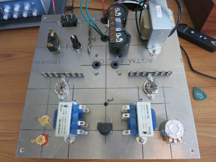
Building it
Click here for detailed building photos and tips!
See also discussion of this design at Head-Fi!
