

The Man, the Myth, the Legend
Peter Millett was born the same night that the biggest, baddest, most butt-rockingest twister ever hit the state of Texas. All the ambulances that night were out saving people’s butts and so his mother had to hitch a ride to the hospital in the town funeral director’s hearse instead. Some say this is why Peter Millett cannot die. When he was delivered, the storm was caught completely off-guard and became very apologetic. It promptly put all the houses and trees back where they were and has since joined an anger-management support group.
When Peter Millett was eight years old, he got a ham radio license. At fourteen, due to a freak cattle stampede that brought down a key control tower, he successfully directed all air traffic over the lone star state for ten days straight with just a tube radio, two rolls of aluminum foil, and a box of flares. After ten days he was a little hungry, so he ate the cattle.
Peter Millett has been an electrical engineer since before it was cool. In April of 2008 he designed the Millett Starving Student Hybrid headphone amplifier because he got up one morning, with a heart full of love and generosity, and noticed that there were good people who didn’t have good sound. That he can’t abide.
The Millett Starving Student Hybrid was the first tube amp I ever hand-wired from a schematic. Pete Millett is my hero. This is a tribute.
The Tube
The original Starving Student used the 19J6 double triode (two in parallel per channel). Unfortunately, the success of the design eventually wiped out most of the affordable stock of the tube. Variations with other tubes have come and gone, but many were a square block stuck in a round hole. I think we can do better (not that I would ever criticize experimentation).
The low B+ voltage provided by the 48V wall wart power supply is an obstacle for a lot of tubes. Similarly, the power supply’s current cap of 0.38A is an important consideration when it comes to the heaters. What we want is a high perveance tube (meaning it can swing the anode closer to 0V) with a high heater voltage. For a given amount of power in the heaters, higher voltage will mean lower current requirements because:
Power = Current * Voltage
There is such a unicorn tube and it is called 7370. The 7370 is a 5687 (medium Mu, high perveance) twin triode with a 20V parallel, 40V series heater arrangement. At 40V, the 7370 heaters draw 130mA, leaving us 250mA for the rest of the circuit. Tits.
Luckily, the 5687/7370 also has some pretty baller plate curves:

Now with a 48V B+, we’re still going to be operating the tube outside of where we’d ideally like to be. But that’s ok. Low voltage is the place to cut your teeth. And, we can actually use a 2-3x Rp plate load and put a couple mA through the tube while still keeping the grid negative. This isn’t a tube forced to work at low voltage against its will. It’s pretty realistic operating conditions, just scaled down.
ENHANCE!

With a 10,000 ohm load, we can set the quiescent anode voltage at half the B+ (24V). That’s a current of 2.5mA through the tube and a grid voltage of -1V. The grid has about 1V swing in either direction. 2V peak to peak is about 0.7Vrms for maximum output. You can get almost that amount (0.5Vrms) with an iPod or smartphone.
The above suggests a 400 ohm cathode resistor (1V / .0025A). In practice, I found that a 750 ohm resistor gave me a 24V anode voltage. This will be relevant for reasons further down the page. In any case, the cathode resistor value can be played with to a certain degree. In the below detail, the anode voltage will fall on the green dashed line (representing the 10,000 ohm anode load) between the red dashed and blue dashed lines (400 and 750 ohm cathode resistors respectively). The anode voltage varies by about 5V between the two.

With an overall gain of roughly 8-9x, the amp is perfectly capable of damaging your hearing. But the tube can’t do that alone. It’s going to get some help from the dark side.
Chips, chips, chips
I know what you’re thinking. You’re thinking this isn’t a tube amp anymore because there’s a MOSFET coming. And I said this was a tube amp and now I’m a liar and a meanie. Although I am wearing hot pants, I assure you it has everything to do with my naturally hairless thighs and nothing to do with false advertising. The tube is the only thing doing any voltage amplification. The solid state parts are basically an awesome strength-enhancing exo-skeleton that turn the tube into a cargo-loading, alien-spanking, mecha-valve. Tube is the brains in the mecha suit, just like Sigourney Weaver (whose legs also look great in hot pants).

The MOSFET
Like the original Starving Student, we’ll use a MOSFET source follower as a current buffer to lower output impedance and feed the tube a steady diet of spinach. MOSFETs are not unlike triodes in some ways. The enhancement mode n-channel IRF510 starts conducting when there is a voltage between drain and source (like a tube’s anode and cathode) and the gate is sufficiently positive (whereas with tubes we want the grid to be negative). It is a lot like a cathode follower but one that can pass current in amps instead of milliamps.
Our power supply provides up to 48V at the drain of the MOSFET. We want the gate of the MOSFET to be somewhat lower than this so that it can swing up and down with AC signals. About half would be good. Hey…didn’t we set the tube’s anode at half of the B+?
CCS
Like a tube, the MOSFET needs a load. Like a cathode follower, with a source follower we put that load between the source and ground. Like a tube, the best load has a really big AC impedance. You read the page on CCS loading so you know where this is headed. Like the Bad Hombre, we can use a LM317 and set the current easily with a single resistor. We have about 250mA to play with, so let’s set the two CCSs (one per channel) to 100mA and try to not blow up the power supply.
Because our supply is 48V, it’s a good idea to use the high voltage (“HV”) version of the LM317. On start up with cold heaters, the CCS will drop close to the supply voltage and so the 60V max on the LM317HV gives us a little more security.
The LM317HV as a CCS is set with a single resistor from output to ground. The adjust pin is connected directly to ground. The LM317 will try to keep 1.25V across the resistor, so the current it passes to do so can be calculated as I = 1.25 / resistor. For 100mA, we need about 12 ohms.
Direct-coupling
We have a grounded cathode amplifier with a bias point that puts about +24V on the anode. We have a MOSFET with +48V on the drain that’s biased by a CCS. We want the gate of the n-channel enhancement mode MOSFET to be able to swing as much as possible with AC signals, so we want it to bias at about half of the supply voltage. That’s +24V. We don’t have to use a coupling cap here because the DC voltage at the output of the tube is the same DC voltage that biases the gate of our MOSFET where we want. Less parts is good. We direct couple.
Of course we don’t want the DC voltage on our headphones though, so we’ll still need an output coupling cap. We can calculate the needed value as:
uF = 1,000,000 / (2 * Pi * f * Zhp)
Where f is the -3db roll off point in hertz, Zhp is the impedance of the headphones we want to use, and uF is the value of the cap (in uF). For a 10hz frequency and 32 ohm headphones, we want about 470uF. Nice that this is a standard value, isn’t it?
Schematic
Put it all together (along with a volume pot and some extra resistors to prevent oscillation) and this is what you get. Click here for PDF schematic (includes tube pin numbers).

Bill of Materials
Part of the fun and excitement of building your own gear is in sourcing all the parts. Here is a list of parts with some suggested vendors and part numbers: Estudiante BoM. I typically buy most things at Mouser, Digikey, and Tube Depot. Don’t take these parts as gospel; make this amp your own!
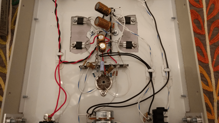
Construction Pics
You can put it together in lots of ways. Here’s what I did (click for construction gallery):
Fiddly Bits
Heatsinks
The TO-220 devices will dissipate a couple of watts each. I used a big heatsink from my parts stash and mounted everything to it. If you don’t have an awesome parts stash, use the heatsinks from the original Starving Student or similar. And start collecting junk and stuff. Quick thermal calculations suggest that a thermal rating of 5-7 C/W per device should leave a good safety margin.
One of the pins on most TO220 devices is connected to the tab internally. If the metal bolt holding the tab to the heatsink isn’t electrically isolated, the internally connected pin is also electrically connected to the heatsink by way of the bolt. On the LM317, the output pin is internally connected to the tab, and on the IRF510, the drain pin is internally connected to the tab. You must use both an insulating pad (mica or similar) as well as an insulating shoulder washer when mounting the TO-220s to your heatsinks (see BOM for mounting kit that includes all of the above).
Grounding
Grounding is the blackest of the black arts. If I’m not doing a straight star ground (all grounds going to a single point), my theory is to always keep the high current grounds (the CCS, tube heaters, etc) closer to the ground return (power jack) than the signal grounds (input, output, tube cathodes). I used a bus bar in my build and grounded everything from the input and tube on one end and everything from the power and output at the other end (which was also connected to the chassis). It worked well for me. Pete Millett built the original Starving Student with a blank PCB as a ground plane. His arts are blacker than mine.
Parts choices
The parts listed above are a minimum in terms of wattage and voltage rating. You can go bigger in ratings (not necessarily values) within reason if you want. Critical values are the tube anode resistor, cathode resistor, and the current setting resistor in the CCS. Most of the rest could be tweaked a bit one way or the other.
In conclusion…
With an overall voltage gain of about 8-9x and an input of 0.7Vrms, we’d get 5-6Vrms output or approximately way more power than you need into 32 ohm headphones. It should do a little over a quarter watt (peak) into 32 ohm headphones with 0.5Vrms input (the output voltage of a phone/iPod). This is limited by the current. Into 300 ohm headphones, it should max out around 500mW (limited by voltage).
A source follower has an output impedance of approximately 1/gm. Transconductance of the IRF510 is rated at 1.3 siemens (dA/dV) with 50Vds and 3.4A Id. We’re nowhere near that much current, but I think it’s safe to say that output impedance will be in the single digits. The Starving Student (same Vds and IRF510s, about the same current) has a measured output impedance of 3 ohms.
It was only by the generosity and time of others that I got into this hobby. I hope this design inspires more builders to give making their own amplifiers a shot. You won’t learn everything overnight, but it’s a lot of fun and a very rewarding pastime.
Pete, if you’re reading this, thank you for inspiring me.
