

Note: before you gorge your eyeballs on this genius design, you may want to read up on cathode followers and power supplies.
The Gain Chain
In the current state of hifi equipment, sources are perfectly capable of driving most amplifiers to full output. Modern sources, such as CD Players and DACs, typically will put out between one and two volts RMS. If you send this one to two volts directly into a modern amplifier it will be loud as balls, but it will probably also sound pretty good. That’s because modern amplifiers are designed to only need about one to two volts input in order to achieve their maximum output without clipping (objectionable distortion). Current buffer amplifiers and low gain phono preamplifiers exist and are exceptions to this, but they are not the norm. This all goes to say that, generally, all you want out of a preamp is a way to decrease the volume of your source without crapping up the signal. This looks like a job for DIY.
Passive preamps have recently become a popular option to serve these ends. A passive preamp is just a simple switch to change between sources and a volume pot (or stepped attenuator). That’s cool and minimalist and all, but if you don’t respect impedance, it will take a hot dump all over your sound quality. Ergo– that’s Latin for here’s the punchline— what we want is a way to decrease the volume of our source, while also providing a low output impedance to the amplifier. You know what will give us that because you’re a smart cookie and you read the cathode follower page.
Te presento Muchedumbre
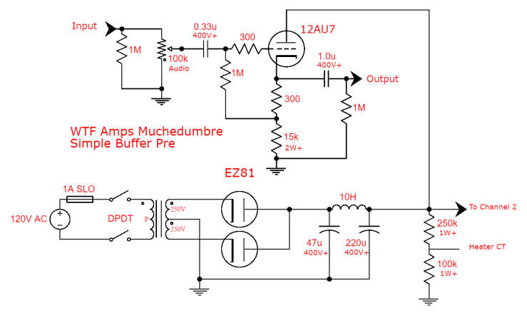
The Muchedumbre is about as simple as anything has ever been or will ever be in vacuum tube audio. It sounds much better than anything this simple has any right to. It’s also damn cheap if you build the chassis yourself and don’t get freaky with the coupling caps or NOS tubes. The Muchedumbre will work with any amplifier’s input impedance of 10,000 ohms or more and will drive long interconnect cables without suffering any roll off of the high frequencies.
Here is the graphical load line for the Muchedumbre:

The 12AU7 has a 15k ohm load resistor (blue line). At the operating point (red x) chosen, the tube, like an em-effing champ, is passing about 10mA of current. The cathode is biased at about 3V above the grid courtesy of the 30o ohm cathode resistor and 1 megaohm (that’s one million ohms) grid leak resistor. If the preamp is connected to an amplifier with a 10k input impedance (a worst case scenario), the tube will operate on the orange load line (15k in parallel with 10k). Maximum dissipation is the dotted red line. We good.
We can estimate the transconductance of the 12AU7 at about 3.3 mA/V. We know that in a cathode follower the output impedance is approximately one divided by Gm. So we have about a 300 ohm output impedance. That’s a whole lot better than any passive preamp can achieve. Because cathode followers inherently have 100% negative feedback, they’re also very linear. That means they stay the hell out of the way and let your jams jammy jam.
Bill of Materials
I was able to source all of the parts for this build from two suppliers (if I don’t count the lumber and aluminum plate that I used for the chassis). Click Here for a PDF BoM. Cost as of June 2016 from these vendors is about $100.
Also, click here for an alternative Octopart BoM courtesy of Adam Keim. Adam Keim is a solder slinging, parts finding, puppy rescuing, golden eared badass and you now owe him a beer.
Notes on specific parts
Caps
The input coupling capacitor (.33uF) can be much smaller without sacrificing bass. The input impedance will be approximately the grid leak resistor (1M) divided by one minus the gain of the stage. The gain of the stage is almost one so the input impedance is yo-mama-huge. You could use a coupling cap a hundred times smaller (.0033uF) and not notice any roll off of the bass. The bass will have a -3db point at frequency (f) according to the following:
f = 1 / (2 * pi * C * a bigass number)
I spec’d .33uF here because I like the Cornell Dubilier 940C series of caps and this was the cheapest in that series. That’s all. Feel free to experiment.
The output capacitor should stay around 1uF or higher. With a hypothetical 25,000 ohm input impedance on your amplifier, this cap will create a -3db point around 5hz. With a 10,000 ohm input impedance, it will be around 15hz (and I might raise it to 1.5 or 2uF in that case). Most tube amplifiers have a much higher input impedance, so you probably won’t need to worry about this.
Power Supply Stuff
The power transformer is an Allied 6K88VG. I like this cute little bugger and the price is right. You can use whatever will give you at least 40mA at 500VCT and 1.5A at 6.3VCT. For 240V/50hz mains, the Hammond 369JX looks like a good alternative.
The power supply uses a tube rectifier. You could also use solid state diodes (eg UF5404’s). I’m using a tube rectifier here because I think having one tube (the 12AU7) sticking out of the preamp looks weird. Seriously, that’s my reasoning there. Your B+ voltage will be slightly higher with solid state, but don’t sweat it.
The power supply filter is CLC. The Triad C-3X choke is cheap as hell and available lots of places. A choke is a big improvement over a resistor, but if you absolutely cannot use a choke, use a 500 ohm 2W resistor or thereabouts.
Other Sundries
The volume pot can be whatever you like in the 50k-250k audio taper flavor. The Alps Blue Velvet series is fine, though becoming harder to find. Stepped attenuators, on the other hand, are becoming easier to find (and cheaper).
I’ve received several questions about the 1M resistors across the input. The great John Broskie has claimed these reduce cross-talk. They are an optional part, so feel free to omit.
The grid stopper value is not too critical but the 300 value shown is about what I use in most cases. If you have left-over resistors in the 270-1k, toss them in.
If you’d like to know what brand of NOS fuse I use in my tube stuff, please let me know and I’ll be glad to slap you in the fecking mouth because that is crazy talk.
Let’s build it
Tools
- Soldering iron: I’ve been using the same 25W Weller iron for years (new tip every few projects)
- Wire strippers: seriously, get yourself a pair instead of trying to use your knife/teeth/wire cutter
- Wire cutter: get a good one that can get into small places when needed
- Needle nose pliers: this is good for ground bus wire, holding hot stuff, etc
- Helping hands: this little gizmo is extremely useful for tasks like splicing wires or holding parts and wires steady while you solder
- Desoldering braid, sucky bulb thing, etc: something to help remove solder when you cock up
Supplies
- I like using 20-22 gauge stranded teflon-jacket hook-up wire for signals; you can use whatever you want, but make sure it has a 400V+ insulation rating
- For things like B+, grounding, and heaters, I use 16 gauge stranded copper PVC jacket wire with a 600V+ insulation rating; it’s nice to have a few different colors
- I use whatever solder is cheap and in my box of stuff
Nitty Gritty
Click here for wiring pictures and tips.
Also more pictures and layout details here.


There’s always room for pudding
And monotonically decaying harmonic distortion spectra:
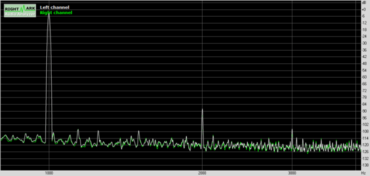
No harmonic above the 3rd is visible in RMAA. Overall THD is measured at less than .01% into 10k line level input with the buffer volume maxed; frequency response is as flat as I trust RMAA to measure. Though not audible in my system, the only measurable issue is 60hz (and harmonics) from the AC and heaters. This could easily be fixed with some time spent tweaking the layout if it keeps you up at night (you freak).
If you want to get funky…
- You could safely swap in a 12BH7 tube for the 12AU7.
- Add more RCA input jacks and a rotary or toggle switch so that you can connect multiple sources.
- Include a bypass switch to switch between passive and active/buffered mode. Note this will probably require that you fiddle with the resistance value of the volume pot because this will determine the output impedance in passive mode.
- Dual mono would be pretty easy and totes rad. Parts cost in the power supply is not much.
- Look for a 12VDC wall wart and a small boost converter for your B+ if you want a snack size buffer preamp (note: don’t actually eat this project).
- Many of the small rectifiers would work fine in this preamp. I chose EZ81 because I wanted to use two of the same socket (9 pin). If you have other 6.3V heater rectifiers and sockets, go nuts.
- The input caps are necessary if using this as a standalone device because the input/grid is referenced to about 1/2 B+. If you want to skip the volume pot and add this as a tube output in the same chassis as another source (DAC, CDP, etc), the input caps can be omitted IF the source’s output caps are rated for at least the tube circuit’s B+ (300v).
Update 2018: a White Cathode Follower version, the Muchedumbre XL (read about it in this blog post):

