

I’ll be honest: this page is kind of mathy. If you don’t like that, just google some calculators you lazy turd (that’s what I do). There are two common ways of hooking up parts in a circuit: “in series” and “in parallel.” In fact, these are probably the only two ways you need to know about. Both terms, series and parallel, are in relation to the voltage source. That might not mean anything to you yet, so here’s a picture:

Resistors and capacitors react differently to these arrangements because they’re total bellends and they want to make your life harder. When stuff is in series, there’s just one path, so the current (flow of electricity) through everything on the path is the same. When things are in parallel, there are multiple paths for current, but the voltage across the paths is the same. In the battery on the right, imagine that instead of red and black wires, the resistors are connected directly to the battery terminals. Voltage is just the difference in charge potential, so the resistors will see the same voltages from the battery at the same points, right? F#$kin-a-right.
Resistors
Series
When in series (battery on the left), resistor values just add together. Cake. The current through the circuit will be determined by the total resistance. So let’s say we have a 9V battery with a 3,250 ohm and a 1,250 ohm resistor in series. What is the current flow?
First, figure the total resistance:
R(A) + R(B) = R(total)
3,250 ohms + 1,250 ohms = 4,500 ohms
Then use Ohm’s Law to find the current:
V / R = I
9 volts / 4,500 ohms = .002 amps (2 mA)
Now how much voltage is there across both resistors? Back to Ohm’s Law:
I * R = V
.002 amps * 3,250 ohms = 6.5 volts
.002 amps * 1,250 ohms = 2.5 volts
That right there is called a voltage divider and it can be real useful when you combine it with parallel circuits.
Parallel
Alright, let’s try parallel. Remember, in parallel the voltage across both resistors will be the same, but the current is divided because there are multiple paths. Use the same 3,250 ohm and 1,250 ohm resistors and figure the current through each of them.
V / R = I
9 volts / 3,250 ohms = .00276… amps
9 volts / 1,250 ohms = .0072 amps
So your total current flowing in the circuit is .00276 amps + .0072 amps. Let’s round it up and call it .01 amps. Then what’s the total resistance of the circuit? Darn tootin’ you’re going to use Ohm’s Law.
V / I = R
9 volts / .01 amps = 900 ohms
So when you connect the two resistors in parallel, you get less total resistance? Yep. Remember our banana talk earlier? Well then feck off and read it, I’ll wait. Now imagine the parallel resistors are like two conveyor belts going across your banana factory. Two conveyor belts together are wider than either single conveyor belt by itself, right? Yes. Lower resistance, more bananas.
If you are lazy (like me) and need to do this shit on a calculator (like me), then the total resistance in a parallel circuit is the reciprocal of the sum of the reciprocals of the resistors in parallel. Brain matter everywhere. It’s goes like this:
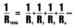
Smart@sses will notice that calculating the total resistance example on a calculator with the equation above gives you 902.8 ohms. Yes, this way is easier and more accurate than finding the individual currents, rounding, and adding them up. So why didn’t we do that in the first place?

Capacitors
Series
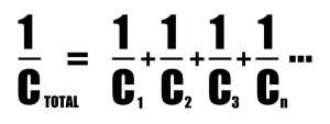
You might not ever need to really use this. Honestly. Just buy the right size caps, you jerk. If you must know, caps in series work like resistors in parallel. Yeah, that reciprocal of the sum of the reciprocals crap:
Parallel
Sometimes this might be useful. Mostly, it’s important to know that capacitors in parallel act like resistors in series. Just add up the values. You’ll see a lot of boutique bypass capacitor BS in power supplies and output caps to “improve the sound.” Jury is out on how much this helps*, but at worst it’s just adding an extra little bit of capacitance to a circuit. No biggie. All things being equal, more is generally more when it comes to capacitors in audio**. I’ll assume you know how to add and can figure this one out, but let me know if you can’t and I’ll be happy to slap you in the fecking mouth.
*The theory is that film capacitors are more linear with regards to frequency than electrolytic capacitors. But high value film capacitors are humongous and expensive, so you bypass a large value (and cheap) electrolytic with a small film cap and get some benefit at higher frequencies. Try it sometime and see what you think. In any case, it can’t really hurt.
**Another disclaimer? WTF, WTF? Blocking distortion recovery time, RIAA accuracy, blah, blah. Happy?
