
Using Tube Curves
Usually I begin building a project with a particular part or parts; often this is a power transformer that was either cheap or scavenged (because I’m a deadbeat tube head). This means that my B+ voltage is already ball-parked by the time I start looking at tube graphs and load lines. We’re going to look at the following triode curves as if we knew our B+ would be just over 200V because it eliminates a design choice and simplifies the explanation. If you start with a big budget and a tube that you want to maximize, you’ll have more flexibility in choosing operating points, but the basic concepts will be the same. And also, f#%k your big budget.
Resistance Loaded (driver or preamp stage)
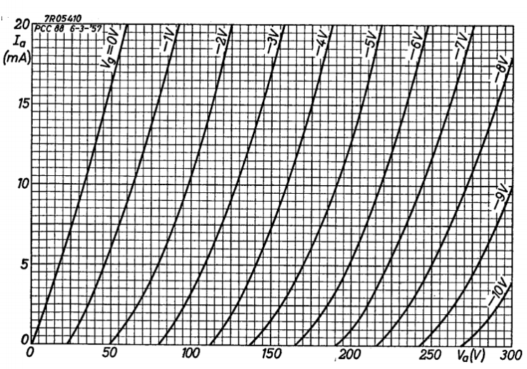 Here is the curve chart for a particular dual triode tube that is pretty popular in audio. If you know what it is, please send me an email and I’ll congratulate you with a slap in the mouth because what it is is not important right now. The vertical axis is current through the tube in milliamps (mA) and the horizontal axis is voltage dropped across the tube in volts. Those frustratingly curved lines across the graph represent the voltage at the grid (AKA grid lines). By making just a few decisions with regards to your design, you’re able to plot the behavior of your tube on this graph. Usually those determining factors are things like bias voltage at the grid, current through the tube, maximum dissipation allowed, B+ voltage available, and so on. We already know our B+ voltage is about 200V for the purposes of this explanation, so let’s get started.
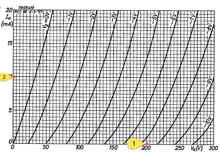 1: This being a resistor-loaded amplification stage, we’ll start by marking two important points on the axis of the graph because these two points are relatively easy to figure out. One point will be where the voltage across the tube is maximum. This is the point where the tube’s high resistance drops nearly all the 200 volts in our power supply and cuts off the current flow. In (x,y) coordinate terms, this point is (200V, 0mA).
2: The second point is determined by the load resistor you want to use. Imagine that your tube completely craps the bed and directly connects your anode resistor load to ground. With the tube out of the picture, how much current will the resistor allow through? It will of course be your B+ voltage divided by the load resistance (Ohm’s Law, natch). I’m going to say we’ll use a 20k ohm anode resistor, so the maximum current in this case is 200 volts divided by 20,000 ohms, or .01 A (10 mA). That’s point #2 (0V, 10mA) marked on the graph.

3: Now draw a line between those points. Hold on a sec and appreciate this moment because you just drew a mother effng load line. Pat yourself on the back, big Kahuna. As your signal on the grid modulates current flow through the tube, the resulting voltage to current relationship will fall on this line. Grid goes more negative, and it follows the line down and to the right. Grid goes more positive and it’s headed up and to the left. As you no doubt realize, getting this line right is an important part of building tube gear. We’ll talk more about that in other sections though. For now, just stay with me.
4: So you’ve got the load line. Now you need to decide where you want the tube to idle. We call this spot the operating point, the OP, the quiescent point, the idle point, or other things. This will set the grid voltage in relation to the cathode, as well as the current through the tube as it does its thing. I’m going to put my operating point right in the middle of this line because it looks like a good spot. This is between the -2V and -3V grid lines. It looks like -2.75V to me. It’s also right at 5 mA from the axis on the left. To determine what cathode resistor I need to drop 2.75V at 5 ma, guess whose equation I’m going to use. My homey, Ohmie. 2.75 V / .005 A = 550 ohms.
At this stage you are also going to want to make sure that you are not violating the maximum dissipation allowed in the tube. Watts dissipated are volts (horizontal axis) multiplied by amps (vertical axis). At our chosen operating point, we’re at about 100V and 0.005A, or .5W. This tube is rated for over 1 watt dissipation and the points on the load line won’t ever exceed that, so we’re good.
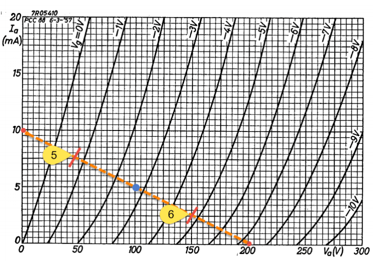
5 & 6: Now that we have a load line and an operating point, we can figure out roughly how much amplification we’ll get out of this setup. If our input is a maximum plus or minus 2V, we can find those points along our load line with the grid. Our grid at the idle point is -2.75V, so a 2V positive signal will push the grid to about .75V (point 5 on the graph). This corresponds to about 50V on the anode using the horizontal axis. If our grid sees a 2V negative signal at the -2.75V idle point, it is pushed to -4.75V (point 6 on the graph). This corresponds to about 150V on the anode. Two volts in either direction will result in about a 50V change at the anode. That’s a voltage gain of about 25 (50V output for 2V input).
There is more to figure out when trying to use this basic design in the real world, but that’s the meat and taters of tube amplification design with a resistive load right there. Booya.
Transformer/Choke Loaded (power or output stage)
You can build a power amplifier for speakers with a resistive load, but it’s about as efficient as taking a backhoe camping just to bury your deuces. More often, tube power amplifiers use an output transformer to both serve as a load and transform the tube power to speaker power. You don’t necessarily need to know why that works to figure out the load line, so we’ll save it for later. For this next group of load line calculations, we’ll use the same approximately 200V B+ as before with a different tube.
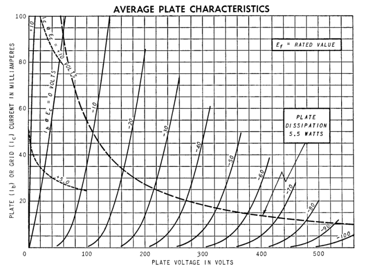 These tube curves look a little different than the ones earlier. Note how much more current is reasonable with this tube. Also, notice that the grid lines are in 10V increments instead of 1V increments. Perhaps most importantly, see how this graph includes the dashed line labeled ‘Plate Dissipation 5.5 Watts?’ Five point five watts is the maximum allowed with this tube, so we’re going to be careful to keep our operating point and load line under this at all times. When this dissipation line is not included on a graph, it is easy to plot out with a marker and calculator. Just choose a bunch of voltages from the horizontal axis and figure out the current that would create the maximum dissipation at each point (W = V * I). For example, to find the maximum current at 300V, we simply divide 5.5 watts by 300 volts and get 18.3 mA. The existing dissipation line passes through this point, of course, because our math is legit as balls.
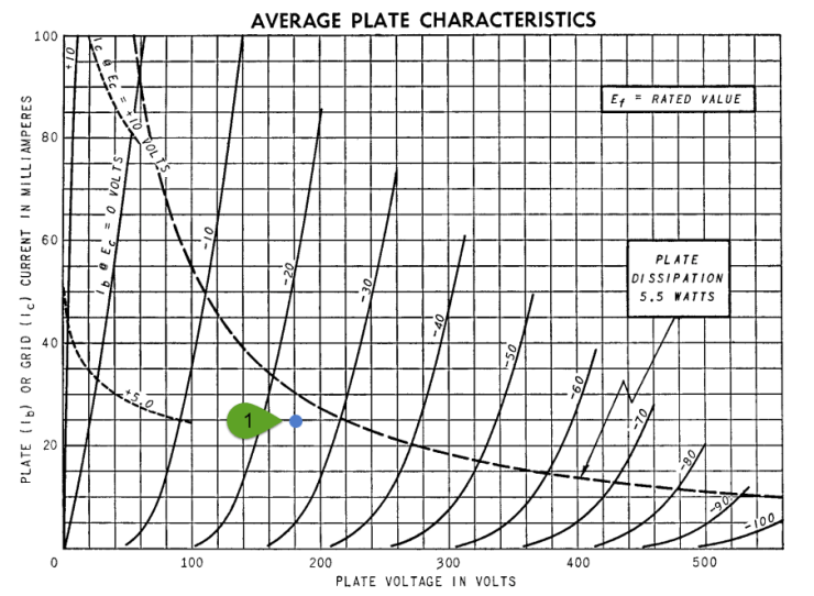 1: Choosing your operating point with a transformer loaded output tube is a little different than with a resistor loaded preamp tube. For one thing, your bias voltage is much bigger and so you have to factor that in if your B+ is already determined and you’re using cathode bias. In our case, we have just over 200V B+ to work with and we want to use a self-bias scheme, so our grid/bias voltage (the grid lines) plus the anode voltage (the horizontal axis) should add to about 200V.
Additionally, an output transformer or choke allows your anode voltage to swing above your supplied B+ because it stores electrical energy as a magnetic field. Your head probably just exploded, so I’ll give you a sec to clean up the mess. Ready? Ok, vamos entonces. This means, in practical application, that you can choose an operating point at the maximum B+ (minus the voltage needed to bias the grid).
Taking these two factors into account, I’m going to choose a point at about 175V on the anode and 25 volts on the grid. Add them up and whatdya get? 200 volts. This will draw about 25 mA according to the vertical axis.

Now we have to consider our load line. Output transformers do not come in as many impedance flavors as resistors and the primary impedance of the output transformer that we choose is what will determine the slope of our load line. Common output transformers are between 2,500 ohms and 5,000 ohms on the primaries. The secondary should be rated for the speaker that we want to hook the amp up to (usually 4 or 8 ohms). I happen to have some 5,500:8 output transformers in my parts bin, so let’s just do that. I’m cheap, remember?
2: We divide the 175V at our operating point by 5,500 ohms to get the current rise from our operating point. This gives us about 32 mA. We add this to the 25 mA at our operating point to find the intercept on the vertical axis. It’s about 57 mA.
3: Connect the points and you’ve got another beautiful load line! You’re starting to feel pretty comfortable with this stuff, aren’t you? This is a good place to note that your grid can swing about 25V positive before it hits the 0V line, meaning it can fluctuate 50V peak to peak (25V above and 25V below our bias point) before we run into any nasty distortion. So you want the signal at the grid to be able to provide at least this amount. Hey, wasn’t that last tube’s load line able to swing these volts…?

4, 5, & 6: Now that we have a load line, let’s figure out how much audio bliss this bad boy wants to stick in our ears. That’s going to require a little math, but don’t worry, it isn’t too bad.
To get the approximate RMS power output, we take the peak-to-peak voltage (between #5 and #6 on the graph), divide by 2 to get the peak voltage, divide by the square root of 2 to get the RMS, square it, and divide by the impedance. It is similar to the wattage equation you already know:
W = V^2 / R
But the audio industry has decided to rate things as RMS just to mess with your head. Now that you know why this is different than the basic equation above, here’s the easier way to remember the formula:
Watts RMS = (Vmax – Vmin)^2 / (8 * Rload)
Vmax (#5 on our graph) is the anode voltage where the grid voltage is twice the bias point grid voltage (#4 on our graph) and Vmin is the anode voltage where the grid voltage is zero (#6 on our graph). In this example, here’s the predicted power:
(290 – 40)^2 / (8 * 5500) = about 1.5 watts RMS
In reality, it will be slightly less due to losses in the output transformer. We can also calculate the power output using the current swing and the W= V * I equation:
Watts RMS = (Vmax – Vmin) * (Imax – Imin) / 8
(290 – 40) * (.05 – .005) / 8 = about 1.4 watts RMS
Again, you lose a bit of it to real-world inefficiency. So we’ve got about a one watt tube amp.

This isn’t the 100W tube amplifier you hoped for, is it? Well, tough titties. Single-ended amplification is almost always below 10W output. To go beyond that, you have to start working with push-pull circuits, which are a little more complicated to design. We will cover that in another section.
