Typically the design process for an amplifier starts at the output and works its way back through the amplification stages to the input (that’s “tooter to the rooter” if you’re hip to pigs). With headphones in particular, this presents an interesting design challenge. Headphones come in many impedance values and this impedance (directly or indirectly) is what determines the tubes’ operating conditions. In contrast, speakers are a pretty standard 8 ohm impedance value, with a 4 ohm here and there. The wide spread of headphone impedance, from 16 ohms to 600 ohms, as well as the relatively low power requirements for headphones, has resulted in a correspondingly diverse array of output stage options.
As a beginner DIYer or headphone amp shopper, the options get confusing. To make matters worse, every manufacturer claims that their solution is the best solution. In the real world of engineering trade-offs, amp topologies are like eating stuff on rice: there is no one best answer for everyone and what you end up liking may surprise you. Don’t confuse this with a claim that there is no such thing as a badly designed or implemented amp though. There are plenty of those to cry over. Hopefully this overview of headphone amp topologies will at least keep you informed as you blow through gear like a circlejerk blows through memes.

Single-ended or differential (AKA push-pull)
Beyond all other aspects, the design choice that will have the most impact on an amplifier design is whether it is single-ended or differential. The difference can be boiled down to whether the output devices handle the entire signal through to the output or “split” the input and then re-combine the opposing phases at the output.
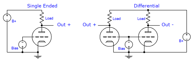
Single-ended amplifiers are inefficient in both a power consumption and economic sense. Because they must be Class A by necessity, they get hotter and require bigger tubes for the same power, increasing cost. Single-ended amplifiers need a squeaky clean power supply to get a respectable noise floor. They tend to produce more distortion, but the distortion that they produce has an even-order-dominated monotonically decaying harmonic spectrum. That’s a fancy-pants way of saying they sound pleasing to the ear. Because you don’t need much power for headphones, the inefficiency of single-ended is usually a non-issue for headphone amplifiers. But don’t underestimate the need for good power supplies.
In contrast, differential amplifiers produce less distortion when designed well, but what they do produce is dominated by odd-order harmonics, which are less pleasing to most listeners. Differential amplifiers are also capable of far more power and efficiency than single-ended amplifiers because they use multiple active devices to amplify opposite phases of the input signal: one device pushes while the other pulls. By nature, differential amplifiers reject power supply noise because they only amplify the difference between the phases and any power noise would appear equally in both.
Both single-ended and differential amplifiers can be output transformer coupled or output transformerless. The distinction between SE and PP is the most fundamental taxonomy that can be applied to amps; the rest is really about how the amp’s output is interfaced with the headphone.
Output Transformer Coupled (OTC)
Tubes are great for voltage amplification, but they have issues when asked to deliver the current required to drive low impedance loads like speakers or low impedance headphones. To put some mathematical perspective on this, the 300B, a directly-heated power triode prized for its low plate resistance, likes to see at least a 2,500 ohm load for acceptably linear single-ended amplification. A speaker provides an 8 ohm load and even high impedance headphones don’t offer more than 600 ohms. So how do we make a pair of 32 ohm Grados into the 2,500 ohms that the 300B wants to see? An output transformer.
Without getting into the specifics of how an output transformer works, they do more or less what the term implies: they transformer. Hooked up between a tube and a headphone, they convince the tube that it isn’t actually connected to 32 ohms, but that it’s connected to 2,500 ohms (or 5,000 ohms, or 8,000 ohms, etc). Of course, no real-world device is perfect and output transformers are not an exception.
The primary challenge when using transformers is finding the right impedance ratio between the input (primary) and output (secondary). Unless the transformer is specially made with multiple outputs (taps), the ratio is fixed and so headphones of various impedance will present different impedance to the tube. Specialty transformers are expensive. Luckily, a properly designed OTC amplifier will not be too adversely affected, aside from making less power into high impedance headphones.
Transformers (AKA mutual inductors) are reactive components and so attention must be paid to their inductance and (unintended) capacitance. These imperfections affect the frequency extremes and addressing them is a matter of amplifier configuration: in part, the SE or PP covered earlier, as well as how the transformer is connected to the tube.
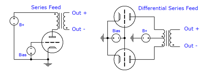
Series-feed and Parallel-feed (AKA parafeed)
As seen in the figure beginning the previous section, a series feed transformer coupled output stage feeds the tube B+ power through the primary of the output transformer. This has a simplicity advantage, which some might say contributes to the purity of the sound. In the case of single-ended amplifiers it requires a ‘gapped transformer,’ which is both larger and more expensive than a comparably rated non-gapped transformer (normally used for push pull). In addition, the power supply ripple travels directly through the transformer primary and is coupled to the output as a result. Differential amplifiers side step both of these potential issues by nature of the way they operate.
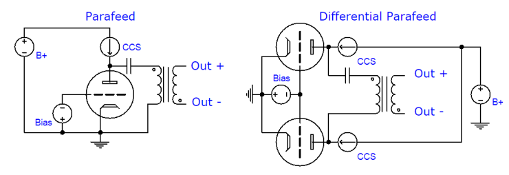
If instead of putting the transformer primary in series with the tube, we put the primary in parallel with the tube, we can reduce the shortcomings (though not without cost). As seen above, a parafeed configuration connects the tube to the primary through a capacitor (which passes signal but not B+ current). This allows us to use un-gapped transformers in single-ended configurations, though we must still provide the tube with a series load so that it has something to bite on. This load is frequently a Constant Current Source (CCS), but it can also be an inductor, resistor, or another tube.
The parafeed arrangement requires more parts (not all of them cheap) and careful math, but provides advantages in some situations. Potentially the most significant advantage is that un-gapped transformers may be used, which may be easier to come by in the size and impedance ratio that works well for headphones. Because the CCS/choke load is a high impedance and the tube is relatively low impedance, less of the power supply ripple appears across the output in comparison to an equivalent series feed stage. But parafeed puts more in the signal path (at least one coupling capacitor more). What if we want even less?
Output Transformerless (OTL)
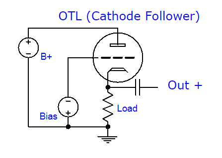
When you want the minimum between your headphones and the amplifying device, OTL is one way to get it (ok, there’s still usually a cap in there though). Output transformerless tube amps almost exclusively use a cathode follower on the output to achieve a low (for tubes) output impedance. Exceptions to the cathode follower stage include the White Cathode Follower or Aikido Cathode Follower variations, and the SRPP.
These are still relatively inefficient ways of driving a headphone, but at headphone levels, inefficiency isn’t a huge problem. Even in an optimized cathode follower configuration though, OTL amps are best used with high impedance headphones. They don’t have the benefit of impedance transformation that an OTC amp would, nor do they have the reactive imperfections. This is, like series feed, a KISS trade-off.
Output transformerless amplifiers typically require an output capacitor for the same reason that it’s required in the parafeed arrangement: DC blocking. We don’t want a couple hundred volts DC across our headphones. Unfortunately, the lower the impedance of your headphone, the larger the value of the capacitor required to pass low frequencies. Low impedance headphones require hundreds of microfarads, meaning electrolytic capacitors (shown to cause distortion in the bass frequencies and exhibit leakage currents causing DC offset and the ‘thump’ on power down). If you exclusively use high impedance headphones, you may be able to use a film capacitor and avoid these potential issues.
Hybrid OTL

Hybrid amplifiers imply a mix of tube and solid state devices. These are a special class of OTL and though they suffer the same electrolytic output capacitor caveat, they are able to work into much lower impedance headphones without distortion created by the active device or severe loss of output power. The MOSFET is a popular choice for an output device and can be configured as a Source Follower, essentially the same idea as the cathode follower above but with much higher transconductance and, therefore, a lower output impedance.
Without getting into the age old butthurt of hollow vs solid state, there should be no doubt that OTL headphone amps are a sensible place to use a transistor over a tube if one is going to use transistors anywhere at all. And if you are willing to use one more transistor in addition, a solid state CCS makes an excellent load for this type of output stage.

If we really want to rid ourselves of the yucky electrolytic capacitor in an OTL amp, we may be able to do so with a bipolar power supply, some differential action, and a bias servo. Transistors are more suited to this arrangement than tubes, one popular configuration being the diamond buffer. The above is a discrete schematic using BJTs, though the same arrangement (in a suped-up form) lurks in the ever-popular BUF634 and LME49600 integrated chips.
Balanced vs. Unbalanced
Balanced is a muddled topic in the headphone world, no doubt due to audio marketing voodoo. “Balanced” and “unbalanced” are types of connections. Balanced and unbalanced are not types of amplifiers. They’re not different numbers of devices. They’re just how one thing gets its voltage signal to another thing.
A balanced connection implies that each phase of an output signal has an equal impedance to ground (or some common point). An unbalanced connection has a single voltage reference (rather than two phases) and a reference to ground. Transducers like speakers and components like amplifiers only care about the difference between the two references they see, whether they are two phases of a signal or a signal and a ground.
Any transformer coupled amplifier can be made balanced regardless of whether it is single-ended or differential. The secondary of the transformer has no fixed midpoint in AC terms, and neither does the headphone. By nature this is a balanced system. Usually we ground one end of the transformer, making it unbalanced. But how much does this affect the performance?
In high noise environments with tiny signals and long cables (like live sound), balanced is awesome because any noise injected into the cable is imprinted on both phases equally, so the difference between them doesn’t change. An unbalanced cable wouldn’t have the same advantage because the noise would not imprint itself equally on the ground and the signal. But if you use your headphone amp on your desk with a two meter cable and a DAC, the common mode rejection (CMR) of balanced signals means diddly.
Balanced and unbalanced are connections. That’s it.