

Warning: this build requires measurement and adjustment of high voltage circuits. This requires excellent safety habits as well as testing equipment like a variac. Some portions of the circuit are best built on PCBs. Though simplicity was part of the design goal for this amplifier, this is not a beginner’s build.
“Everything should be made as simple as possible, but not simpler.”
-Einstein
The monkey on your back
There comes a time in every DIY builder’s life where he or she gets the urge to stretch beyond single-digit output power and single-ended amplification. There is no shortage of worthwhile projects to choose from: variations on Williamson, Mullard, or Dynaco push-pull topologies are easy to find discussed in forums and tweaked to compensate for modern parts. You can even find kits for something like the Dynaco ST-70.
When the double-digit power bug bit me I could not bring myself to abandon my usual no-feedback, triode output, class A comfort zone. This is the simplest (but not the only) path to good sound and my speakers are efficient enough. I’m also too lazy to do feedback math, but that doesn’t mean open-loop, class A triode designs aren’t an engaging challenge. This build faced the following complications (which are common to many push-pull amplifiers):
- Class A requires healthy current in the output stage: this needs to be balanced in the output transformer to preserve inductance
- Two cascaded grounded cathode input stages is too much gain, but one stage is generally not enough
- The input stage must have low enough output impedance to drive the triode output tubes
For the most part, my solutions to the challenges strive for simplicity. As is often the case in tubes and life, simplicity in some areas is traded for complexity elsewhere. This push-pull amp has only two stages, the outputs are cathode biased, and it requires only three tubes per channel. To make this seeming simplicity possible, I used solid state helper circuits on PCBs. While these helper circuits are not technically complex, they drive up the parts count and require some measurement and adjustment.
Here is the conceptual topology for Los Monos:

Pictured is a two-stage triode output push-pull amplifier. The output stage is garter biased and the voltage gain and phase splitter stages are combined in a folded cascode long tail pair. This is all described below. Here’s the full schematic, though I encourage you to read through the write-up to understand my goals and approach to this amp.
Output stage
Triode outputs will give us reasonably low output impedance without using negative feedback. I want the option of new production tubes and at least 10W triode (or 20W ultralinear) output. In directly heated triodes (DHTs), either 2A3s or 300Bs might do. I’d love push-pull 300B monoblocks, but I don’t love the price or the complication of direct heating for this project. Indirectly heated triode-strapped pentodes like EL34 or KT88 are more my speed (and budget).
These octal tubes work well in push-pull configurations with output transformers in the 4-6k primary range. The lower end of the primary impedance range gives more power and the higher end of the range gives less distortion. For these mono-blocks I chose the Hammond 1650N output transformer with a 4.3k primary impedance. This is the same primary impedance used in the hugely popular Dynaco ST-70, so output transformers (whether salvage, OEM, or upgrade models) shouldn’t be hard to find. With multiple secondary configurations and ultra linear taps on the Hammond, it can also be setup in configurations offering higher primary impedance (e.g. 8k6:8) or more power (ultralinear) to suit the speakers it will be paired with.
No matter what output transformer we use, we’ll want to balance the current through the two phases in order to preserve inductance (i.e. bass). Because we’re looking to operate in class A, we should try to keep the tubes from blowing themselves up with runaway current, too. Our two primary methods of biasing are to apply a negative voltage directly to the grid (AKA fixed bias) or to raise the cathode potential with the voltage drop across a cathode resistor (AKA cathode or auto bias).
Fixed bias has an advantage in initially setting idle current very accurately, though it can drift over time as the tubes age. If we’re operating close to maximum dissipation specs (and we’re also lazy about checking and adjusting things like this), that could be a problem. Cathode bias is a looser but safer “set it and forget it” option for class A but it doesn’t match current as accurately.
Beyond the prototypical approaches, there are variations on fixed and cathode bias that we should consider as well . A bias servo applies a negative voltage to the grid but monitors current through the tube and adjusts the grid voltage to keep it at a set value. For high current applications, the bias servo nanny is a nice safety feature. It comes at the cost of complication though: usually a couple of opamps, transistor buffers, and a suitable power supply per channel.

Cathode bias likewise has a nifty variation that has been detailed on TubeCAD and elsewhere. Garter belt bias uses two cathode resistors in series under each power tube. The power tube grids get their DC reference from their partner’s cathode network rather than ground. If one tube begins drawing more current, the drop across its cathode resistors increases. The partner tube’s grid, which is referenced to the junction of these cathode resistors, becomes biased less negative relative to its own cathode, increasing conduction. The tubes each sense their partner and find a current balance. The garter belt variation is an elegantly simple solution that still retains the current limiting advantage of regular cathode bias.

The price we pay is in the extra voltage drop at the cathodes of the output tubes (twice as much as regular cathode bias). This effectively reduces the amount of B+ we can use to produce power, so we will want to preserve what B+ we have available with solid state rectification and low voltage drops in the filter. For this build, I will take this trade-off and save myself the complication of extra bias voltages or power supplies in fixed bias approaches.
Datasheets for the EL34 suggest a class A push-pull operating point of 400V @ 65mA per tube into a 5k load, giving us 16.5W. This sounds like a good place to start calculating, given our goals. The triode loadline for one EL34 into 4.3k anode-to-anode looks about like this:
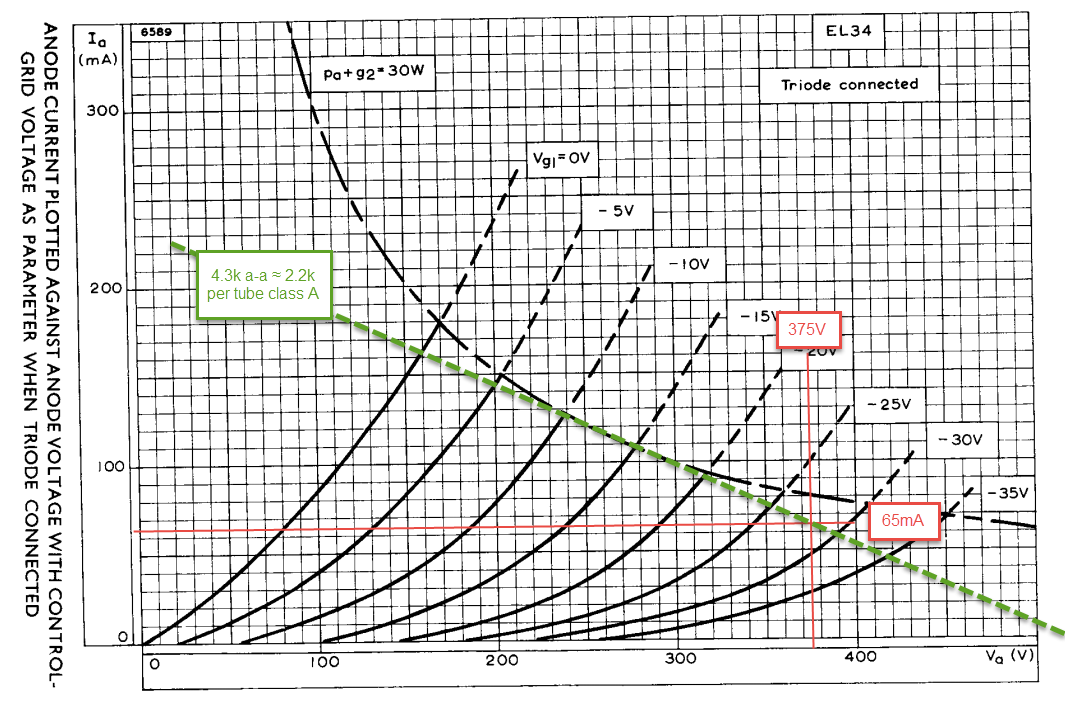
Maximum anode dissipation on an EL34 is 25W (or 30W a+g2 if you believe the Mullard datasheets) so this bias point takes it close to the limit. We’ll use 470 ohm cathode resistors to bias the cathode up by about 30V. Because we’re using garter bias, we add a second set of 470 ohm resistors in series with the first pair to create the cross-reference point between tubes (this also means twice the voltage drop in the cathode). The cathode bias resistors will be bypassed with at least 220uF 100V+ capacitors.
Based on the loadlines, our power output is approximately 20W when our grid hits 0V:
2 * (V quiescent – V min)² / Primary Impedance (anode to anode)
2 * (375 – 150)² / 4300 ≈ 20W
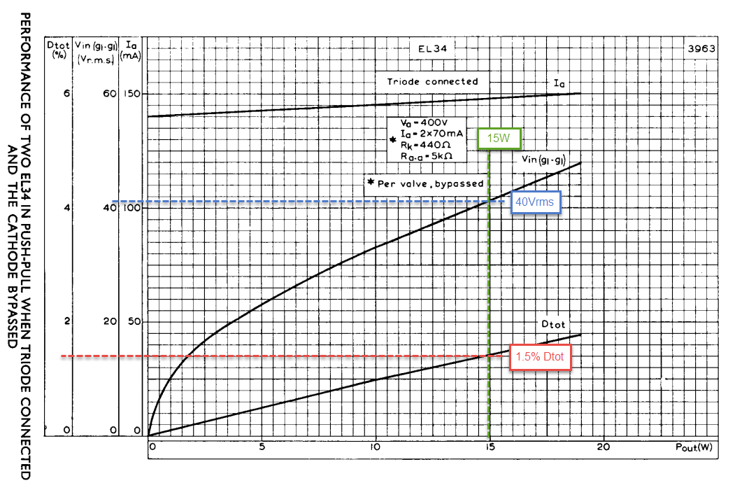
And if we tolerate a little distortion, we may be able to get a bit more. This 20W calculation is just a little bit higher than the Mullard datasheet suggests with similar operating conditions. Sigh, no one makes datasheets like Mullard anymore:
These decisions in the output stage make our raw B+ requirement about 435V (375V + 30V + 30V). The Hammond 274BX is the same physical size as the 1650N output transformer I’m using, has plenty of heater current, and I should be able to get 425-450V B+ out of it with a simple filter. This works out nicely due partly to serendipity and partly because I already chose the power transformer before I did most of the above math.
With the same B+ supply, you might eek out another watt or two by skipping the garter bias scheme (thus having more voltage anode to cathode). I built my amps with garter bias so that I could use EL34s that I had lying around. One of these little jerks blew up a cathode bypass cap (bad tube) so I ended up buying a nice set of matched Mullard tubes anyways. Still I don’t mind giving up a small amount of power for the knowledge that current in my output transformers will stay well balanced as the tubes age.
If you’re looking for more power, keep the garter bias and connect the outputs in ultralinear. Ultralinear mode allows the anode to swing much closer to 0V, like a regular pentode would, but the local feedback from the transformer taps reduces output impedance and distortion to levels similar to triodes. Mullard has a graph for that too:

Now you know why I sprang for a set of Mullard tubes (yes, I know they’re really made by New Sensor).
Input/driver stage
With the output stage grids biased at roughly -30V relative to their own cathodes, we know that we’ll need to swing 60V peak-to-peak on each EL34 grid for full output. Each EL34 handles one phase (i.e. half) of the signal, so the stages driving them will be doing this twice for each channel. If our goal is a 1V p-t-p input for full output, and that input signal will be ‘split’ to drive the push-pull outputs, we need a gain from the first stage(s) of at least 120 (i.e. gain of 60 for each phase). One volt peak to peak is a pretty small signal (about 0.3Vrms) so we can relax this ballpark gain requirement somewhat and still get full output from even most phono stages.
Rightfully respected amp designs like the Williamson or Mullard 5-20 have way more open loop gain than we’re seeking. These amplifiers use the extra gain to apply negative feedback and linearize the amplifier’s behavior. This results in excellent measured performance. The challenge with this approach in a DIY amplifier is the capricious stability of high feedback and parts variation. If you’re building with parts on hand or improvising, high feedback can create problematic and potentially damaging oscillations when it isn’t carefully calculated. So, in the interest of both creating an accessible circuit and avoiding extra math, this amplifier will not use negative feedback.
That detour was the long way of saying that we don’t want a whole lot of excess gain from the input stage. Something in the neighborhood of 90-120 times voltage gain is about right. Where multi-stage designs will tend to produce too much gain, few single-stage options will both produce enough gain and maintain low enough output impedance. A long tail pair based on the 12AX7 with Mu of 100 would get us close and a MOSFET source follower could help the high Rp dual triode drive the output tubes (see the EL34 Baby Huey project for this approach). Call that a one and a half stage solution.
Allen Wright took a slightly different approach to a two stage push pull amp. His PP-1C and PP-2C amplifiers employ a long tail pair made up of cascodes at the input. The cascode’s high bandwidth and high gain (relative to a grounded cathode amplifier) are both valuable features in this application, but the topology also has liabilities. Relatively low PSRR threatens to leak PSU ripple into the signal and potentially high output impedance might have trouble driving triode outputs. The output impedance of a cascode is roughly equal to its loading resistor and this resistor also sets the gain (approximately Rl x Gm of the lower tube), so high gain leads to high output impedance (holding transconductance constant).
Luckily, our target gain may be out of reach of most tridoes, but it is not extreme for a cascode. We should be able to achieve enough gain without output impedance getting too high. For example, given a lower tube with Gm of 8mA/V, we’d need a load resistor of 12.5k ohms to realize a gain of 100. An output impedance of about 12.5k ohms is plenty low to drive our outputs in this application. Even if we lower the transconductance with some degenerative cathode feedback (to balance and linearize the long tail pair) we can keep output impedance below 20k ohms with the right lower tube. This still allows even for a 220k resistor to reference the output tubes’ grids to ground (the maximum value for a triode-connected cathode-biased KT88).
The second hurdle is the poor PSRR of the cascode circuit. We get some noise cancellation due to the differential nature of the long tail pair, but it may not be enough. Allen Wright employed a high impedance filter in the PP-1C and a ‘SuperReg’ in his PP-2C to feed the cascodes a clean supply. While researching cascodes and PSRR, I came across an intriguing twist: the folded cascode (AKA shunt cascode). Ale from Bartola Valves has a fabulous write up on this flavor of cascode. Its primary advocate, Rod Coleman, also sells shunt cascode kits. Both of these gentlemen were a huge help while I was designing the input stage of this amp and developing a PCB for it to live on.
Enter the (hybrid) folded cascode
The most relevant strengths of the folded cascode in the context of this project are:
- No ‘upper’ tube or extra heater windings required compared to vanilla cascodes
- A ground referenced load resistor improves PSRR over a vanilla cascode
- The shared CCS for the folded cascode devices creates a constant current draw from the PSU
- The transistor ‘upper’ device passes current variation, but does not amplify the signal
- Like a vanilla cascode, gain is set by the load resistor and can exceed the tube’s Mu
- Sufficient gain and low output impedance can be achieved in a single stage
Here’s a conceptual outline of the folded cascode amplification stage that I built for this project:

Reading left to right on this schematic, we have a fixed current through a bypassed resistor to create a DC voltage reference, a CCS loaded emitter-follower to buffer this voltage reference, and lastly the combination of p-channel transistor and tube known as a folded cascode. The p-channel transistor in this combination is biased by the buffered voltage reference. This keeps its emitter locked at roughly the reference voltage. The tube’s anode, attached to the transistor’s emitter, is therefore also locked at the reference voltage.
Good dual-triode candidates for this front end can achieve a transconductance of around 10mA/V. For reasons discussed shortly, we want to realize this transconductance with around 120-150V at the anode. The 6DJ8 is a go-to for cheap transconductance, but the target anode voltage may be cutting it close depending on which datasheet you’re reading. For this build I chose 6N6P (or ECC99) tubes with their higher voltage and dissipation ratings.
Usually we think of voltage signals on the grid of a tube creating voltage changes across an anode load. With high impedance loads like constant current sources, current doesn’t change much and loadlines can be represented as basically horizontal lines on anode curve charts. In the case of the folded cascode, a constant current source sets the total current through the tube and transistor, but division of current between them is still allowed to vary with signal. The transistor’s emitter voltage is set by the reference at its base and the emitter voltage in turn sets the anode voltage for the tube. Current, not voltage, is allowed to vary. That means we’re dealing with a vertical, instead of a horizontal loadline.

It is at this point that I realize how much we’re trying to cover in this write up. If you are having trouble following the details of the input stage, please read Ale’s article and wade through the diyAudio thread on the folded cascode. Ignore the voltage reference and its buffer for a moment. Remember the constant voltage vertical loadline for the tube (which gets the input) and the shared current between the tube and transistor. Think of the transistor and tube as two kids on a seesaw (the total current). The big tube kid is doing most of the work, but that transistor kid is tenacious AF and having the time of his life. They bounce up and down and the current swings back and forth, but the total current remains the same.
The transistor’s most important job is to relay the current changes at the anode of the tube to the load resistor at the transistor’s collector. The current variation through the resistor becomes the voltage signal output faccording to our old homie Ohmie (finally, a familiar concept). Our voltage gain is the change in current per change in grid voltage (AKA transconductance) multiplied by the loading resistor. This is the same gain formula as an all-tube cascode.

Above is the detailed schematic of the folded cascodes. Note the cascode CCSs to set the voltage reference (JFET + MOSFET) and load the tube+transistor (MOSFET + MOSFET). Each of these CCSs are made up of n-channel depletion mode devices (i.e. we bias them just like tubes). The lower device sets a bias voltage between the gate and source of the upper device. The upper device handles most of the dissipation. The reference voltage buffer is a simple LED+transistor CCS like the one detailed here in the post about discrete current sources.
In this long tail pair arrangement we set the current share through the tubes with a constant current sink at their cathodes. This cathode current is subtracted from the current set by the shared current source at the junction of the tube’s anode and the transistor’s emitter. The leftover from this current source becomes the transistor’s quiescent current. For maximum signal swing on the output, we set the current through the transistor so that the voltage at its collector is about half of the reference voltage. In other words, we get the most variation in voltage without the transistor collector hitting 0V or the reference voltage (the collector cannot swing past its own base voltage). I aimed for a reference voltage of about 150V so that I had plenty of room for voltage swing at the loading resistor and a healthy voltage on the anode of the tube.

The cathode CCS (above) is a LED-referenced transistor cascode arrangement. I used this kind of CCS because I wanted something that didn’t require much negative voltage and because I had PCBs already made up for the circuit. Morgan Jones goes into detail about this style of CCS in Valve Amplifiers. Basically, it operates just like the simple discrete LED+transistor CCS from the blog.
Current is set by the lower transistor using an LED as a reference while the upper transistor handles most of the dissipation and is effectively ‘always on.’ Impedance is the product of the hfe of the two devices. For about 30mA (15mA each phase), you’ll need a resistance of 30-50 ohms, depending on the voltage drop of your LEDs. A cascoded BJT may be overkill in this application and a single 10M45S or similar depletion mode MOSFET may work just as well if you have more negative voltage to work with (I’d shoot for at least -24V).
Power Supply
Our target B+ for our output stage is 425-450V (and 170mA+). This calls for a center tapped winding of around 750V with solid state rectification. The Hammond 274BX with a 750VCT @ 200mA high voltage winding, 6.3V @ 6A, and 5V @ 3A is a great candidate that also happens to have the same size laminations as our Hammond 1650N output transformers. There are plenty of options that can meet the same targets, but the aesthetic advantage of matching Hammond transformers is not lost on me here.
Common 1000V rated rectifiers like the 1N4007 or UF5408 look like they might have a short life after some PSUD2 modeling, so I selected 1200V rated HEXFRED diodes in a TO220 package. The rectifier is followed with a CLC filter constructed of 120uF-6H-120uF components. The choke is an easy-to-find Triad C-14X while the caps are a little pricier 500V rated Nichicon. Springing for 600V rated caps is not a bad idea at these voltages, though simulation and measurement of the pair I built says I’m fine with 500V.

Achieving the negative voltage requires a little more circuit creativity than the straightforward B+ rail. Not wanting to add another transformer, I decided to voltage double the 5V winding normally used for a tube rectifier’s filament supply. I’ve used a Delon bridge doubler circuit in the past, even as a B+ supply in small SET amps, so I turned to it again here. The rectifiers feed the two capacitors and charge them up to the AC peak voltage potential. This results in a DC voltage output increased by a factor of two times the square root of two (about 2.8) over the AC input. We leave the secondary of the winding floating and so we can get either a positive or negative output dpending on how we reference to circuit ground. After rectifier drops, I get a little over -10V from this doubler.
In building the monoblocks, I also added a CL90 inrush current limiter between my IEC and fuse (not shown in schematics). This is what’s known as a thermistor. A thermistor has a modest resistance when cold but drops to very low resistance when warmed up by current flow. This slows down our B+ voltage while the heaters are cold and reduces the voltage spike on our PSU caps. The CL90 is a cheap insurance policy in this build.
Construction
Here is the PDF schematic again and here is a PDF bill of materials.
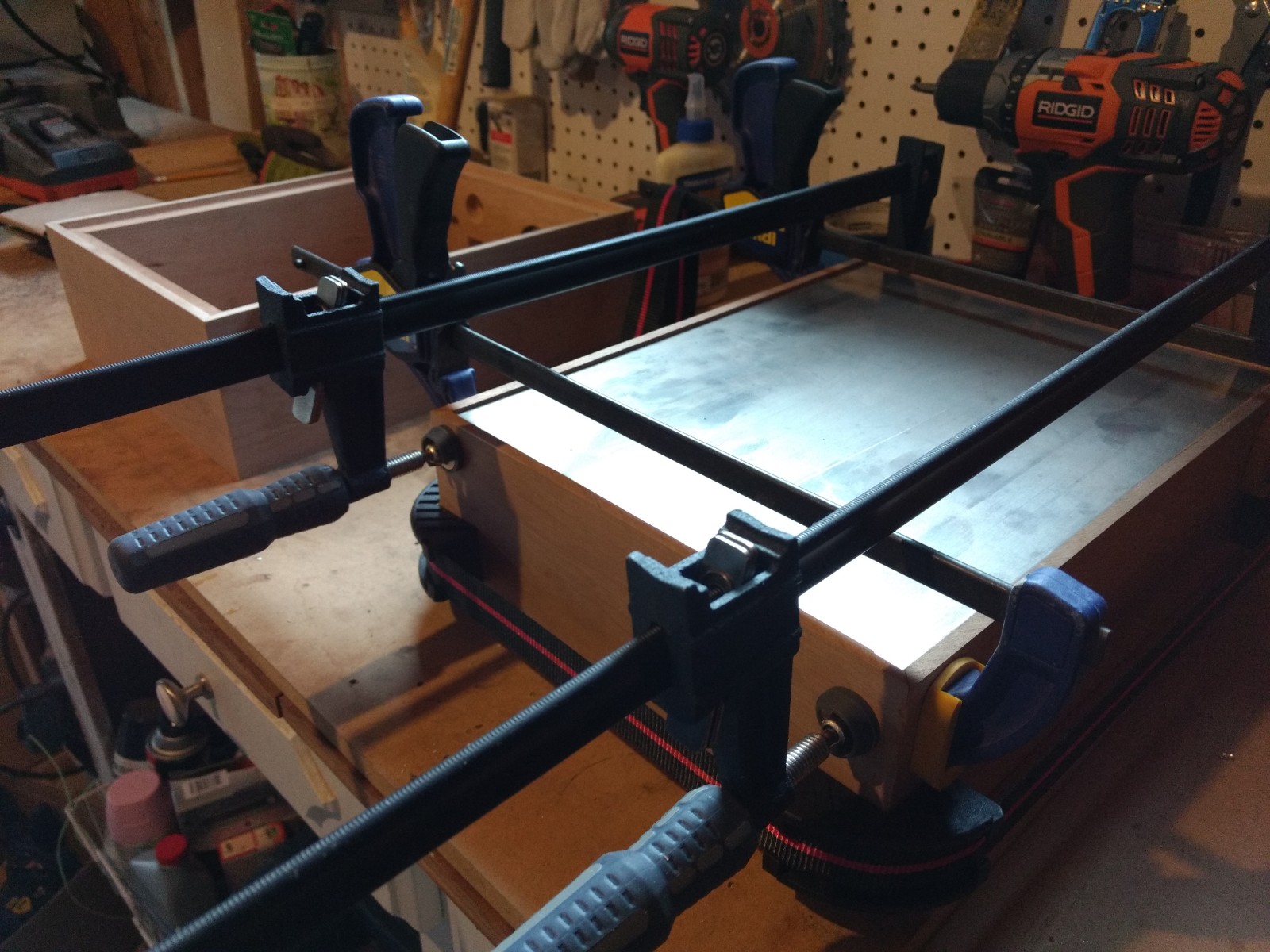
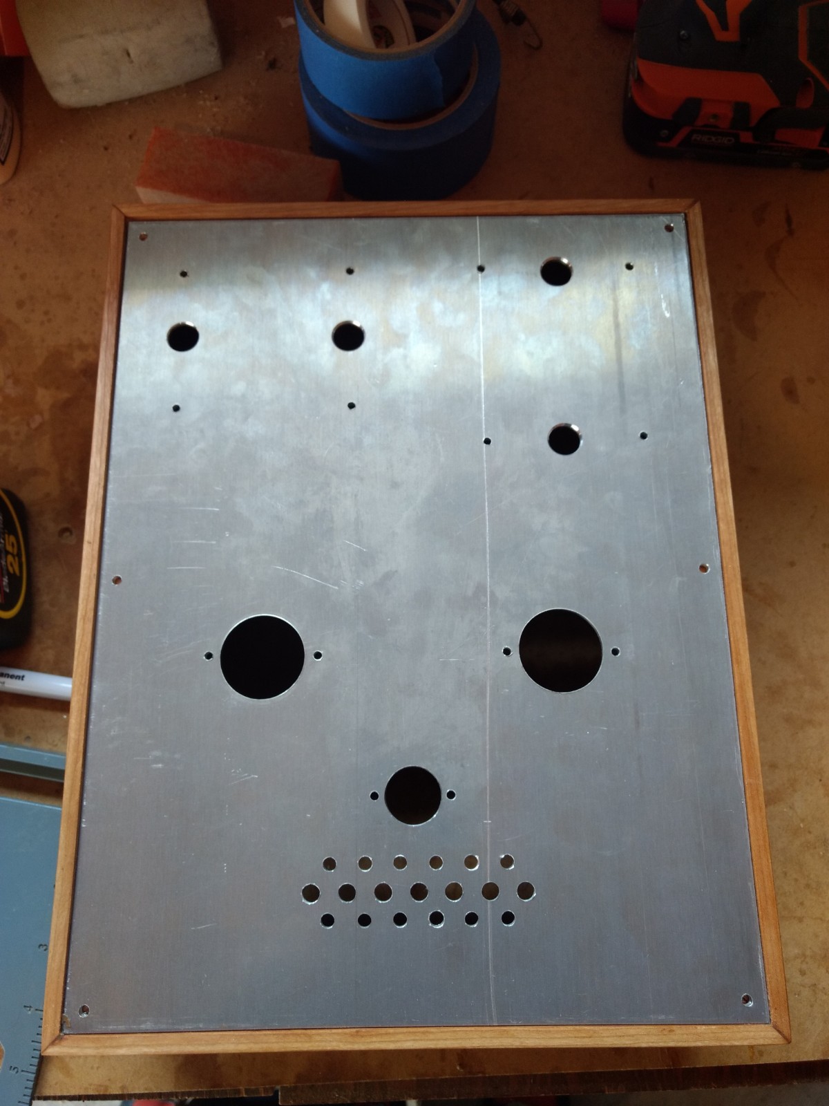
I won’t go into depth on chassis construction as it’s a similar approach to the one you see here. The top plate is regular 6061 1/8″ aluminum. I drilled the socket and vent holes on a drill press using a trick explained here. The finish is a Danish oil using more or less the method explained on the can. No hocus pocus here, just old fashioned craftsmanship (i.e. dude in a garage with power tools and a can of beer).
I’m not gonna lie, these monoblocks took me a long ass time to build (like close to a year). Now part of the reason was that I was in graduate school and had a toddler at home, but it was also because integrating the solid state PCBs into a fairly small enclosure along with a bunch of high voltage parts required more problem solving than my usual straightforward tubes-and-passive-components build. In fact, once I was satisfied with the layout and testing of the first channel, the second one went together in just a couple weeks. Should you venture to replicate this build, here are some tips on construction based on my experience:
- Aluminum angle is a great and inexpensive material for making PCB mounting brackets. A common hacksaw will make quick and accurate cuts.
- Invest in small hardware parts like stand-offs and nylon washers.
- Don’t be afraid of tearing the wiring apart and rebuilding; I tried a couple of ground schemes before settling on one that was silent.
- Pay attention to board orientation and your trim pots; I’d have easier adjustments if I bought trimmers with the adjustment mounted on the side.
- There are several heatsinks in this build and double the normal drop in the cathode circuit of the output stage, so plan your chassis venting accordingly.
The folded cascode PCBs

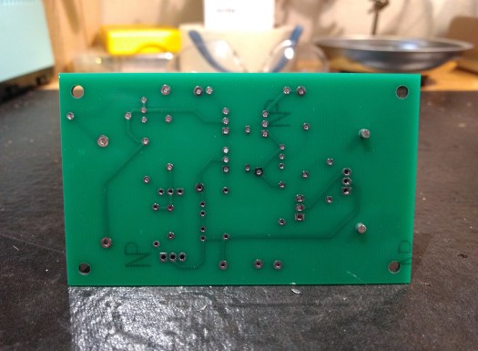

I designed the folded cascode PCBs with operating voltages up to around 300V in mind. This is limited by the voltage and dissipation limits of the ZTX558 p-channel transistor. In the monoblocks the raw B+ is dropped to the right range by a simple RC filter. On setup and testing, I used the following steps to adjust the voltage/current at the input of the amplifiers:
- Without tubes installed, power up on a variac to 300V on the boards (note that the variac may be necessary because without tubes drawing currents our voltage levels at various points in the circuit will be higher)
- Adjust voltage references on the boards to 150VDC
- Adjust anode CCS so that output is at approximately 75VDC
- With power off, set the cathode CCS for approximately 30mA
- Install input tube and power up again to approximately 300V on the boards
- The output will now likely fall to 0V because the cathode CCS is stealing all the current. Increase the anode CCS setting until you see approximately 75VDC on the output.
- Check current through cathode degeneration resistors, adjust cathode CCS if necessary and readjust anode CCSs
- Install output tubes and power up fully into a dummy load
- Check output tube anode and cathode voltages to be sure they’re close to expected (60V at cathode, 435V at anode, give or take a few percent)
- Give it a listen!
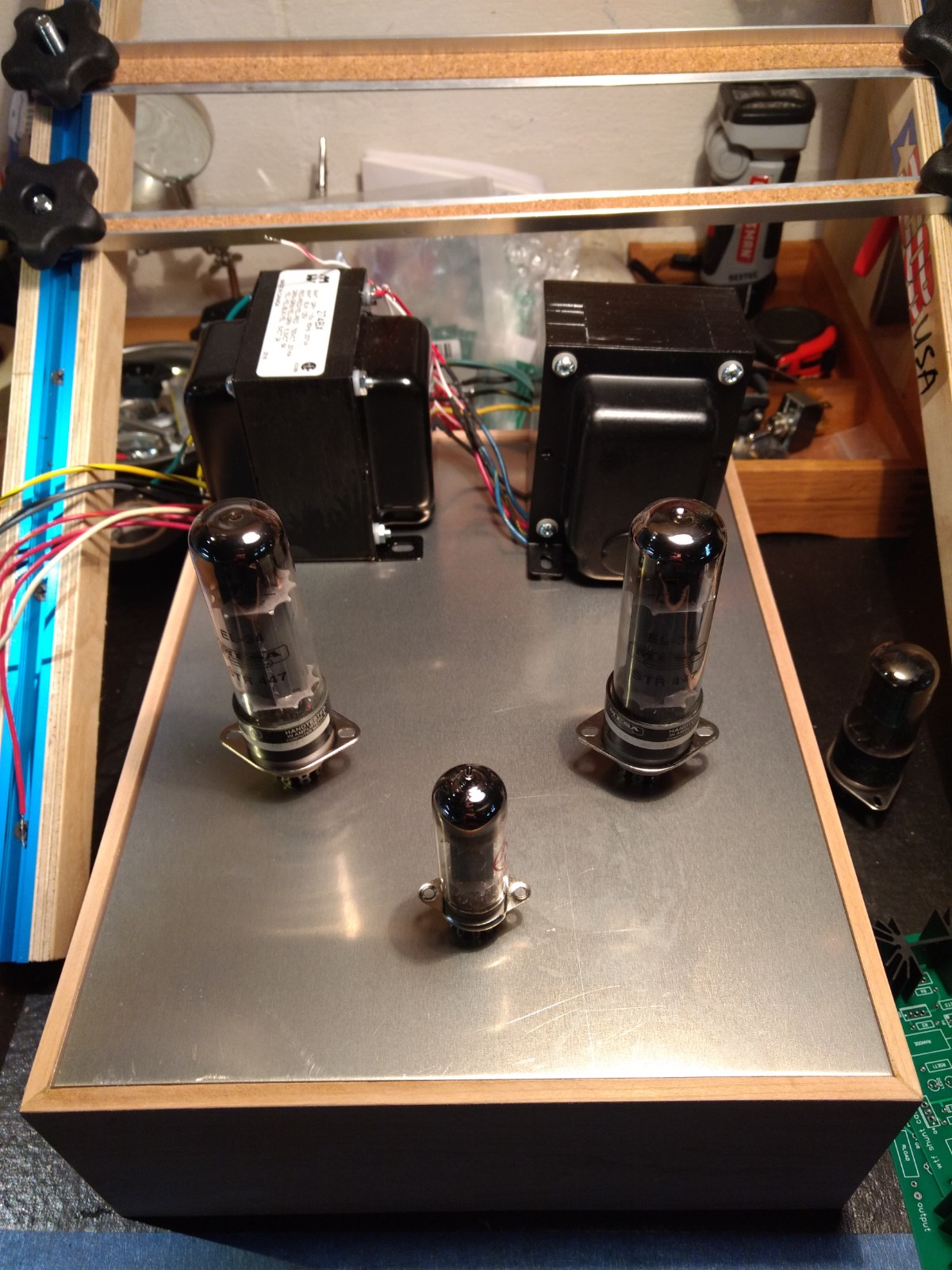
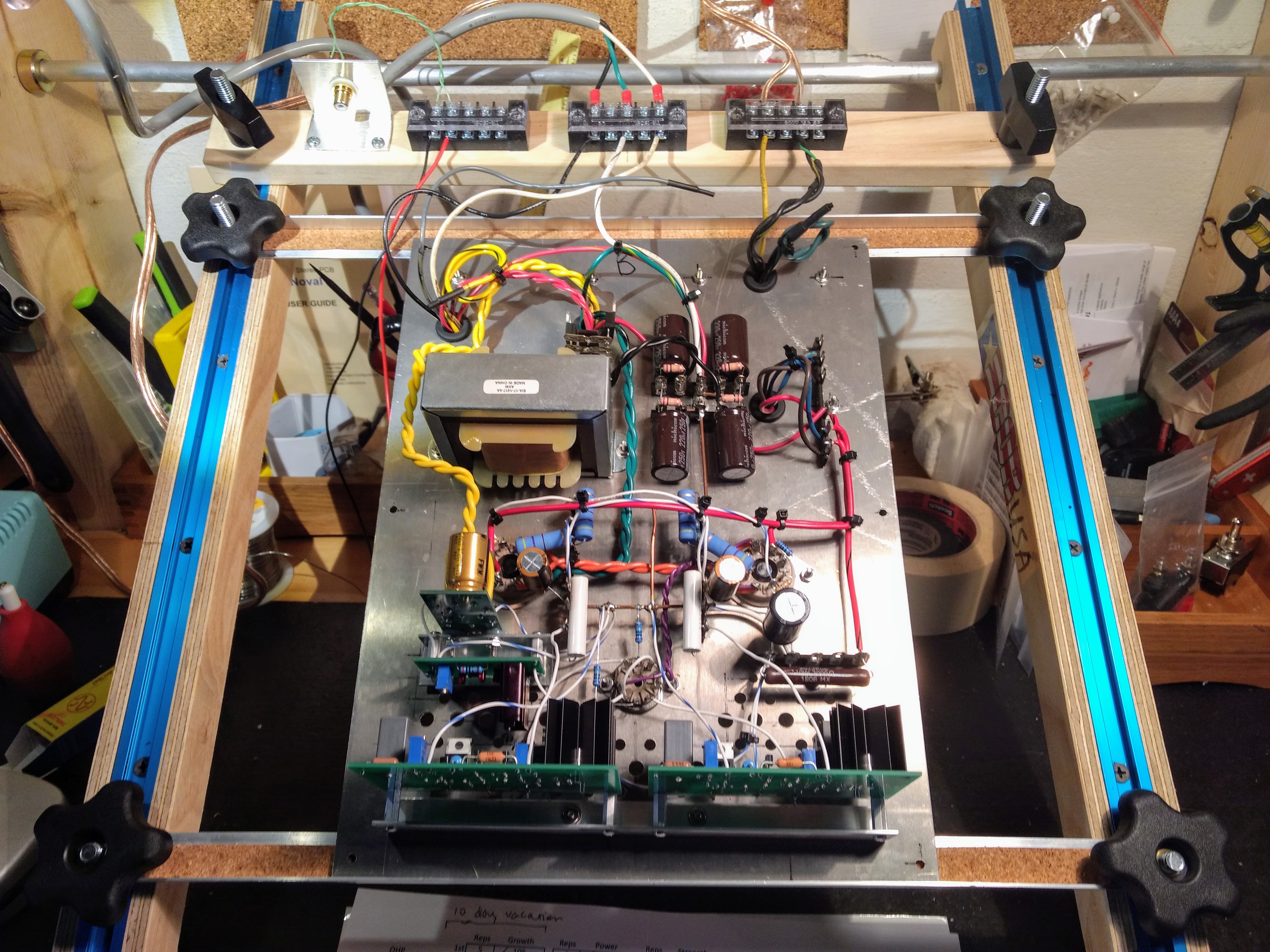
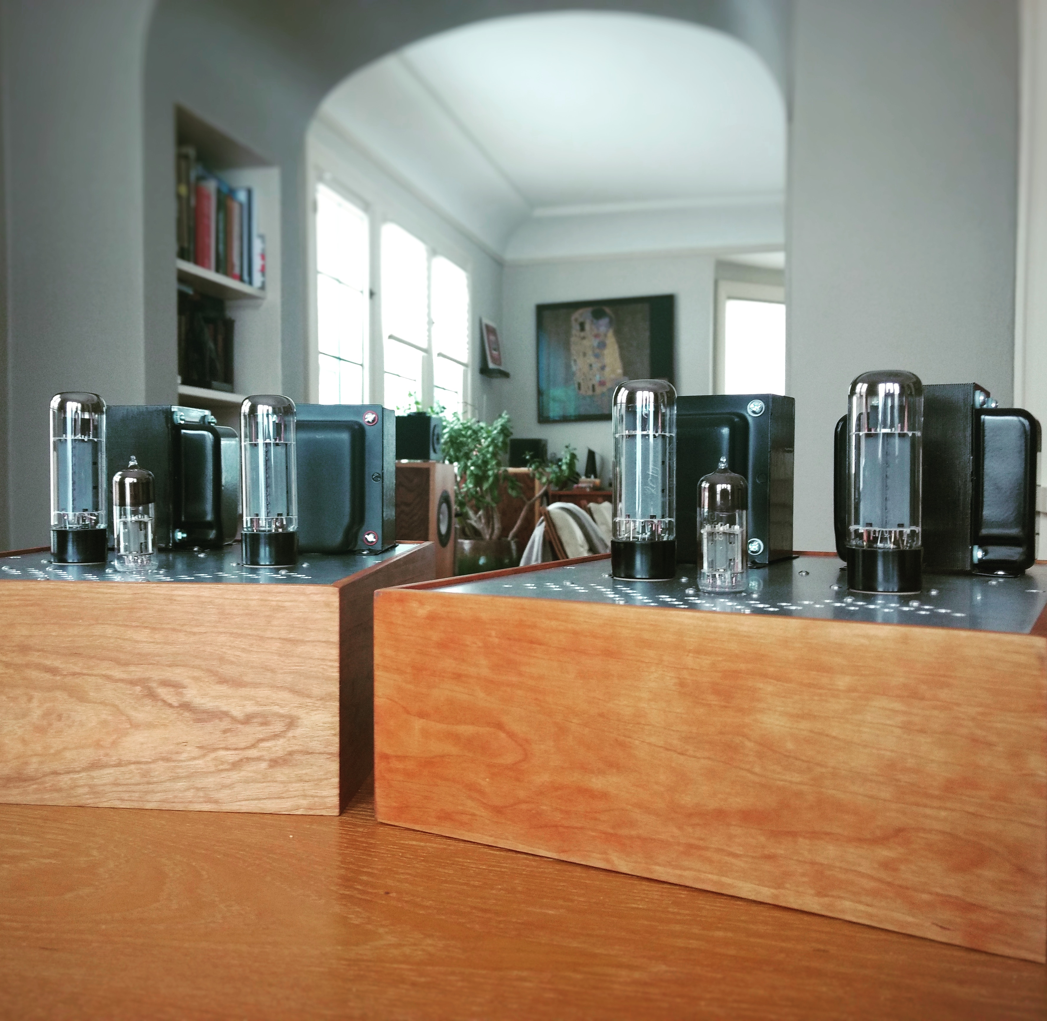
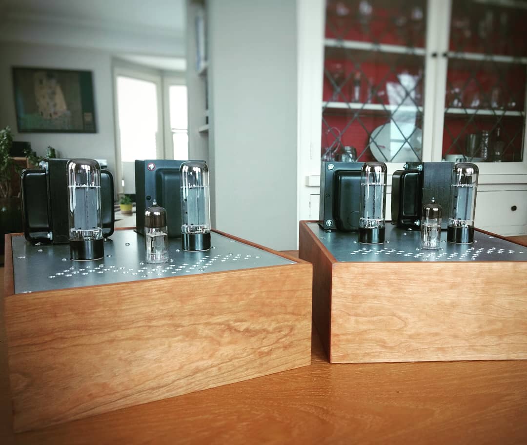
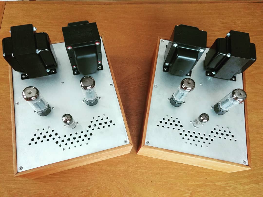
Build pics


Parting thoughts
This ‘simple’ build turned out a bit more complicated than it looks in concept. I think my next couple of builds will be back to basics, but when I’m ready to revisit the folded cascode I’m intrigued by some of the possibilities.
- With all the potential gain from the input stage, this is an interesting candidate for AB2 drive. This would require a supplementary bipolar power supply and I’d use MOSFET source followers for the grid driver (in fact I already have some boards designed).
- While you’re at it, you might as well return the shunt cascode load resistor to a negative voltage rail and direct couple to the AB2 driver. For peace of mind, I’d incorporate a bias servo to keep it well-behaved (yes that gets quite complicated).
- The schematic as built might also work fine with KT88 outputs. These would draw more current and end up pretty close to the specs of the Hammond 274BX. I also like the looks of KT66 but these would definitely require a change in the cathode resistor value.
- I wired my outputs in triode but I will probably add a switch for ultralinear. Mullard’s claimed specs at about the same operating point are too good not to try out.
I can see why guys like Ale and Rod praise the folded cascode. In single-ended applications it would be a less fiddly gain stage than this long tail pair (fewer CCSs to adjust). It would especially shine driving low Mu DHTs like 2A3 and 300B. I’m also very curious about the folded cascode as the front end of a phono preamp and picked up some 6S4P tubes to try (Gm ~20mA/V).
These monoblocks were a large project that I undertook at a really busy stage in my personal life. In a way, they were a culmination/dissertation project that took a bit of everything I knew how to do up to this point. I hope the write-up is an interesting read even for builders who do not follow me down the rabbit hole. For those that do, my hat’s off to you. In my biased opinion, these are a very special pair of amps. It’s not every day that you hear triode push-pull class A amplifiers with only two stages and no feedback.
