
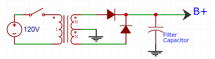
We full wave rectified our AC into DC, but it’s still pretty bumpy looking isn’t it?

Smoothing out the ripple in your DC falls to your power supply filtering. This is typically a combination of capacitors, resistors, inductors, and/or brute force to turn that shitty pulsing voltage into nice, flat, placid voltage (that can kill you). Filters do so by blocking or shunting the AC component of your rectified voltage to ground and only passing the DC component, but we’ll use an analogy here to make things a little easier to visualize.
/ButthurtEngineerDisclaimer
Capacitors
Imagine our pulsing voltage coming out of the rectifier is buckets of bananas being tossed onto a conveyor belt. The bananas are on their way to be peeled by hand, and for that to happen efficiently, the bananas need to arrive at a steady rate. To create a steady rate out of an unsteady supply, conveyor belts often use hoppers. The buckets of bananas go into the hopper, a bucket at a time, and a smaller conveyor moves them on at a consistent rate that doesn’t deplete the hopper supply.
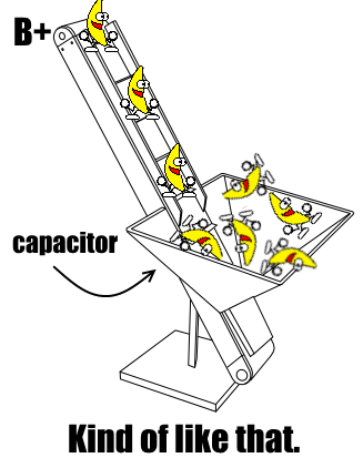
As long as our hopper is big enough and the rate at which the bananas are removed from it is low enough, this is a pretty good way to smooth out the delivery of bananas by the bucket. In this analogy, a capacitor is like the hopper. It stores bananas/current that is simultaneously being used by the rest of the tube circuit. We also call this capacitor a reservoir capacitor, for obvious reasons.
“Why not just use a bigass capacitor, then?” you ask, awash in the delight of your own cleverness. Well we could, but it would probably be huge and super expensive. The rectifier might also blow itself up when it tries to send a crap-ton of current into a huge empty capacitor. Large value, high voltage capacitors get really huge, really quickly, too. So slow your roll, cowboy.
Resistors, CRC
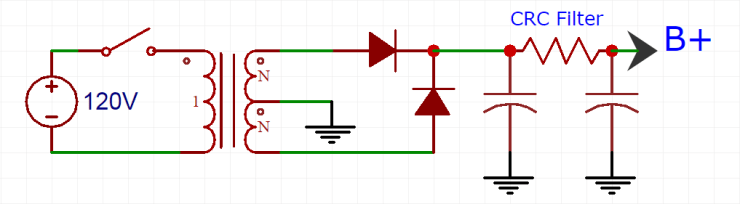
Instead of using one ginormous capacitor right after your rectifier as a shunt/reservoir, it is better to split the capacitors and connect them with a resistor. In addition, the CRC, capacitor-resistor-capacitor, arrangement has advantages over a simple capacitor:
- It slows down the surge of current caused by powering up with empty capacitors
- It creates a low-pass filter that helps diminish high frequency ripple in your B+ voltage
- It allows you to tweak the value of your B+
The last point is maybe the most useful. If you know how much current your amplifier is going to draw, you can calculate how much voltage you’ll drop across the resistor in the CRC with Ohm’s Law. This lets you drop your B+ voltage to something appropriate for the tubes you’re using. You’ll often also want a different B+ voltage going to different parts of your amplifier. That can be done with sequential CRC filters (ie CRCRC, CRCRCRC, etc). When calculating your voltage drop, make sure to figure out how much wattage the resistor will dissipate (W = V^2 / R).
Inductors, CLC
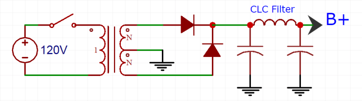
Using a CLC (capacitor-inductor-capacitor) filter has several disadvantages:
- Inductors (AKA chokes) are usually big, heavy, and expensive
- Inductors create a magnetic field that may interact with your transformers
- Big power inductors are a specialty item and so are harder to find
But, a simple choke filtered power supply does a much better job of eliminating AC than a capacitor or CRC filter. Chokes, like power transformers, work by storing energy as a magnetic field. This magnetic field resists sudden changes in voltage (like the ripple that comes from a rectifier) and, when calculated correctly, only pass smooth, steady current. They are high impedance devices. That makes chokes and CLC filters a much more effective device for reducing the ripple in your power supply than a resistor.
Chokes are rated in Henries at a specified current. Beyond a certain current, chokes will still pass current, but they will no longer offer the same AC rejection (this is called saturation). The choke should also specify a DCR (direct current resistance). This DCR number works like a simple resistor when calculating the voltage drop across it. Because chokes are just wire wrapped around a chunk of metal, they typically have a fairly low resistance. Those with lower current ratings use thinner wire and so have a higher resistance; the opposite is true of higher current chokes.
Just like CRC filters, CLC filters can be used sequentially. It is also common to combine the two filter types. For example, a power supply that starts with a CLC filter to minimize ripple, can be followed by a CRC filter(s) to drop the B+ voltage to the needed level (eg CLCRC).
In order to get this superior AC-rejection performance, you have to live with the trade-offs of size, weight, and expense. That said, it’s very possible to design great power supplies with any of the above filters. What you choose to use is usually up to the specific application and what parts you do, or don’t, already have on hand to work with.
See the Alternative Approaches page for other power supply and filtering styles.
