We throw around the phrase “operating point” or “quiescent point” in tube discussions as shorthand for a whole bunch of different pieces of information. Used loosely, the operating point may refer to anode dissipation, grid bias, class of amplification, even the loadline a tube is operating on. Here I’ll use operating point to mean strictly the cathode current (Ik) and anode-cathode voltage (Va) of a tube at rest (ie no signal). Using active loads, we can usually set one or the other of these parameters very accurately. Which one (current or voltage) we set depends on the goals we’re pursuing.

A constant current source, such as a depletion mode MOSFET, sets a constant DC current through a tube (assuming a perfect device). It is the high transconductance of the MOSFET that allows it to maintain current despite large AC voltage signals at the anode of the tube. The resulting loadline is horizontal. With a horizontal line bisecting the grid lines, we can see that changes in anode voltage are very consistent with respect to changes in grid voltage. This generally leads to lower distortion than we can practically get with a resistor load.
Using an active device, we can alternatively set the anode voltage of a tube and allow the current to vary. The lower tube in a cascode is one such example. In this case, our loadline is vertical rather than horizontal. The tube varies its current with AC signals and this current variation is transformed into a voltage variation across a load resistor (at the “top” of the cascode). The transconductance of the tube and the size of the load resistor determine how much voltage gain is produced; this gain can easily exceed the Mu of the tube.
A series-feed transformer (or choke load) also lets us set a quiescent anode voltage (B+ minus the voltage drop across the transformer’s DCR). Unlike the lower tube in a cascode, a transformer loaded tube still swings voltage at its anode with AC signals. These signals are produced into an inductive impedance that presents no load at DC. That is to say the quiescent voltage is basically constant (for Class A operation) but the AC voltage and current are allowed to swing with the signal. As a result, we have control over operating voltage and still maintain (potentially) high impedance loading and voltage output.
Unfortunately, transformers and chokes are often expensive, hard to source, or both. But lucky us, there’s an alternative active circuit that mimics a transformer/choke load. Ale from Bartola Valves (who also sells a gyrator PCB) has written exhaustively on using “gyrator” loads, especially with DHTs which have sensitive maximum voltage ratings. If you look it up in a textbook, this circuit may fail to fulfill the nitpicky technical definition of a gyrator, but the way it works and behaves is close enough for the name to have stuck in most tube and audio circles.
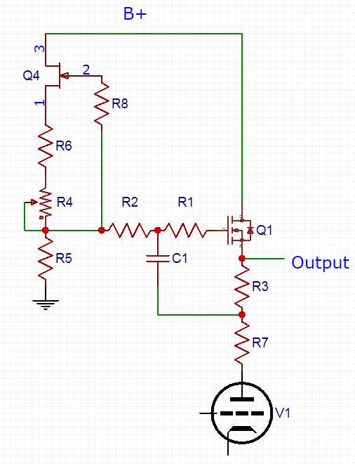
By setting the Q1 MOSFET’s gate voltage, we are setting the voltage at its source. This is the operating voltage for the tube’s anode. If we left it at that, we’d be left with a vertical loadline like we see in a cascode. The magic here is that the capacitor (C1) coupling the MOSFET gate to the tube anode passes AC signals. The higher the frequency, the lower the reactance of the capacitor and the more signal makes it to the MOSFET’s gate to be reflected back to the tube’s anode by the MOSFET’s source. Like a transformer or choke, the gyrator’s impedance therefore increases with frequency. Also like a transformer, the gyrator does not set operating current (like a CCS); it only sets an operating voltage.
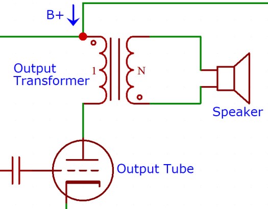
Transformers still hold a key advantage. Unlike the gyrator, an inductor stores energy. This means an inductor load can swing above the supply voltage. This is an important advantage for output transformers where output power has an exponential relationship with voltage swing. It is also important in power supplies where we want to minimize the power dissipated in the filter components (for size, efficiency, thermal reasons). In input stages, where maximum anode voltages of the tubes used are lower and current is generally smaller, the voltage required across the gyrator to accommodate the signal swing is less of an issue. It’s input stage applications like this where the high impedance of a gyrator makes for an interesting alternative to the high impedance of a constant current source.
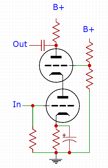
So what? If they are both just high impedance loads, why would I use a MOSFET gyrator with a bunch more parts instead of a MOSFET CCS? Well first of all, stop shouting. Second of all, there are times where setting the anode voltage rather than the current is beneficial. If we want to direct couple one stage to another, the anode voltage of the driving stage will set the grid voltage of the following stage. It’s very important in this situation that the voltage is stable and predictable over time.
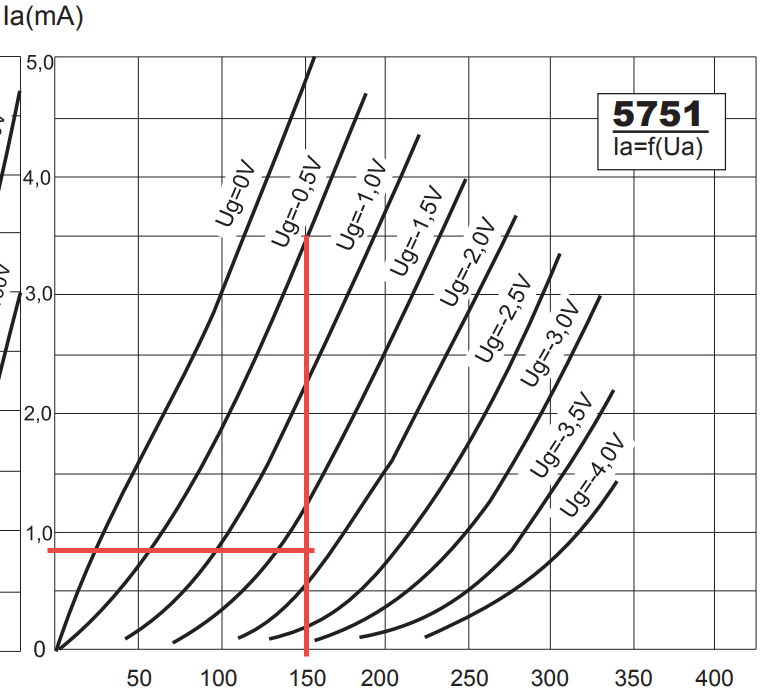
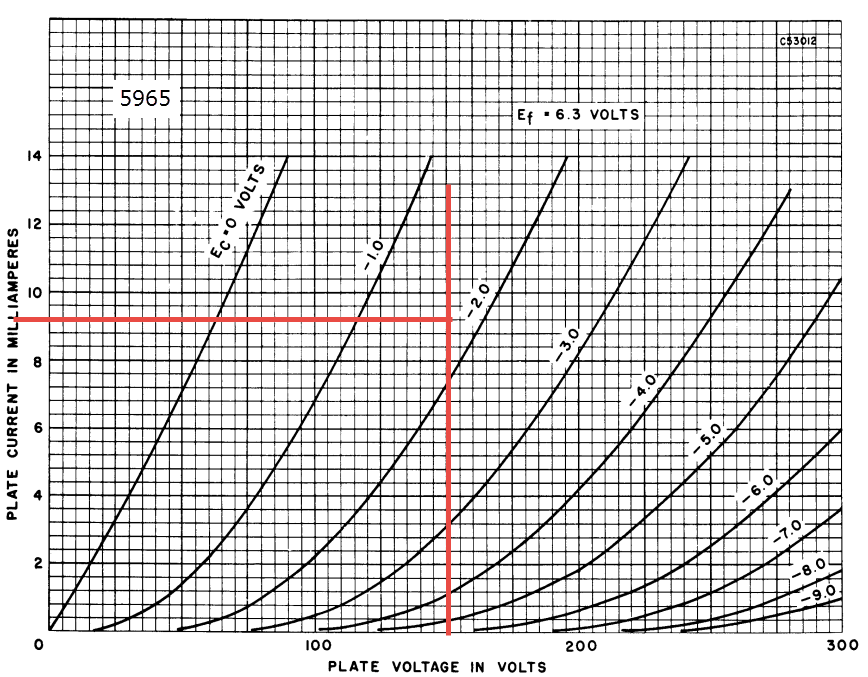
Setting an anode voltage also gives you more flexibility when swapping tubes. A wide variety of small signal triodes are going to be pretty happy at around 150V anode to cathode, even if the current varies quite a bit. In contrast, commiting to a 2mA or 12mA constant current source would severely limit your tube choices. With so many tubes sharing pinouts (12XX7 family, 6CG7 family, etc), it seems a shame to limit our options for sonic experimentation just to save the cost of a couple passive parts.
Here are several examples of the 12XX7 pinout family with 150V on the anode and a grid bias of about -1.6V (e.g. LED cathode bias):