

I really like buffers for line stages. Something about abstinence from voltage gain just gets my inner sonic puritan all hot and bothered. In many modern systems, a “preamplifier” doesn’t really need to amplify. Lots of sources are able to provide 1-2Vrms signals and lots of amplifiers can be driven to full power with the same 1-2Vrms input. All you really need in many cases is volume control. The buffer does a good job of removing any impedance mismatch from the equation without adding unnecessary voltage gain. Unity gain buffers like cathode followers are also sonically transparent stages if loaded realistically. But that’s all so damn rational and conservative, isn’t it?
Sometimes extra gain is useful in between low output sources like phono and power amplifiers, even if it doesn’t look like it is needed on paper (not all vinyl and cartridge combinations will have the same output level). Sometimes a little bit of flavor from a preamp is going to be the right match for your listening tastes and the rest of your system. Sometimes you just want some big glowing tubes to gaze at. If you too feel the need for a little gain and flavor, and a lot of glass and glow, this DIY tube preamp is for you.
Kick them nasty thoughts

Like speakers, size matters in tubes. More accurately, current matters. A bigger tube allows for a bigger cathode and higher voltages, allowing for more current. We know this because of Child’s Law. Paraphrasing:
Current = Constant * Cathode Area * Plate Voltage3/2 / Distance Between Electrodes2
While we could increase current by decreasing electrode spacing (denominator term), there are mechanical limits to the tolerance and size that can be realized in vacuum tube construction. Big tubes also look rad, so there’s that.
More current through a tube generally means a lower plate resistance, in turn leading to a lower output impedance. All other things held equal, a lower output impedance will give us better signal transfer between stages or devices. The typical low Mu in power tubes is a compromise to get a low plate resistance, but in a line stage where we are only looking for modest gain, a low Mu works in our favor.
So we want to look for larger tubes with low plate resistance and modest Mu. I’ll add that for ease of construction and parts sourcing, it should be a 6.3V indirectly heated tube, preferably on an octal base. Also cheap. Cheap is good. Lucky for us, these are not onerous qualifications, so we have a nice selection of potential candidates:
6AH4GT – Mu 8, Rp 1780, Gm 4.5, a true triode, good operating points
6CK4 – Mu 6.6, Rp 1200, Gm 5.5, a true triode, iffy looking plate curves
6W6GT – Mu 6, Rp 1600, Gm 3.8, beam pentode, nice triode curves
6Y6GA – Mu 5, Rp 750, Gm 6.6, beam pentode, low max plate voltage of 200V
6V6GT – Mu 9, Rp 1800, Gm 5, beam pentode, easy to find and well documented
I happen to have pairs of all of the above. If building for myself, I might try the 6AH4GT or 6Y6GA. Both look very good on paper and have some devotees in the audio underground, but neither was especially widespread even when they were being manufactured. The 6W6, 6Y6, and 6V6 are all pin compatible and should find fairly similar operating points with cathode bias, so tube rolling is an option (note the hungry heaters in the 6W6). The 6V6 is easily the most common tube in the list and is in current production from multiple manufacturers. You can also find it NOS in super sexy swinging ST shape glass. Winner.
The 6V6 is what we’ll use in the schematics and loadlines, but any of the above would make a good and simple big bottle line stage. If you’d like to try a different tube, the loadline and power supply process outlined below is the same. If you use the same power supply, the only critical design difference (aside from pinout) will be the cathode resistor needed to keep the quiescent current around 25mA. Load and power supply can then remain unchanged.
Output topologies
Before we start drawing loadlines, we should decide on what kind of loading or output topology we want to use. Because we are not looking for a large amount of voltage gain, active loading (like with a CCS) is not what we want. A CCS presents an ‘infinte’ AC load to the tube, maximizing gain. Too much gain and the volume control will be too sensitive. A CCS will also generally create a more linear stage. While this is desirable in most cases, these tubes are already fairly linear by themselves.
We’re left with passive loading options: transformers or resistors. By using a low ratio output transformer we could achieve an even lower output impedance at the cost of a bit of gain. Unfortunately, low ratio output transformers that tolerate DC current in the primary are not cheap and parafeed would add complication and parts. We want big bottles, cheap, and simple. That leaves us with a resistor loaded grounded cathode amplifier. Classic.
Baby got curves

Given that we are starting from scratch but know what tube we’d like to use, the first thing to do with the plate curves from the datasheet is decide where we’d like the tube to operate. We want the quiescent point in a region where the grid lines are evenly spaced and reasonably straight; this means the plate resistance will be close to constant and provide a good linear response with AC signals. We also want the quiescent point to be below the max dissipation of the tube (not always marked on curves).
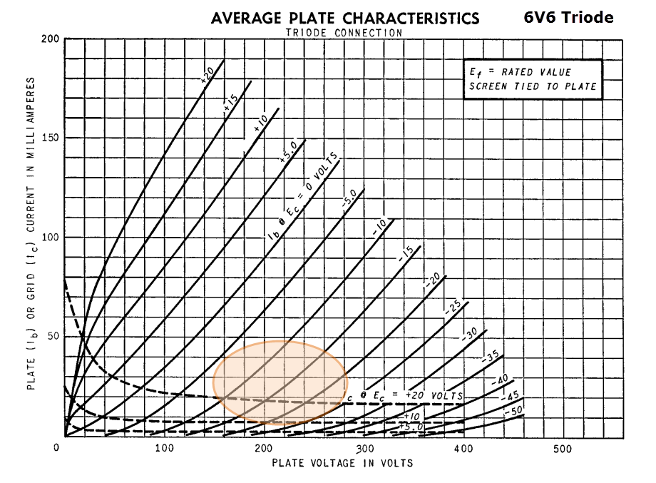
I like this region on the 6V6 triode curves. You can see that the -10V and -20V grid lines are both equidistant from the -15V line and all three grid lines are fairly straight. Because the grid will see at most a 2Vrms (5.6V peak to peak) signal, the plate (and therefore the output of the stage) will swing in a very small section of the curves. If we can put at least 20mA or so through the tube, we don’t have to worry about where the line spacing gets squishy at low current.
Knowing approximately where we want our operating point, we can choose a resistor load value. This will in turn help us determine the B+ requirement. The tubes from the list earlier all have fairly similar plate resistance values (between 1k and 2k ohms), so the same load resistor value will work reasonably well for any of them.
A high value load resistor increases gain and limits the current we’ll be able to run through the tube. A low value load resistor will have less gain and allow higher current, but it will also usually be less linear because input signals will swing the plate closer to the low current squishies. A good compromise value is usually somewhere between 2 and 3 times the plate resistance: 5,000 ohms is a round value and the same impedance we’d usually look for if this 6V6 were transformer loaded.

Here’s a 5k loadline. When drawing this loadline, think about how the tube and resistor will be arranged. The resistor, in series with the tube, will limit the total possible current. For any given supply voltage (x axis) the maximum current (y axis) will be the supply voltage divided by the load resistor value (ie the tube is a short and I = V / R). In this case I drew the line starting at 500V because I know 500 volts divided by 5,000 ohms is 0.1 amps (or 100mA). We haven’t fixed a supply voltage yet, so it’s just the slope of the loadline that matters, not where it crosses the axis.
Now, with the loadline slope drawn, we can move it left (or down, depending on your imaginary perspective) until it passes through the region where we want the tube to operate. Like so:
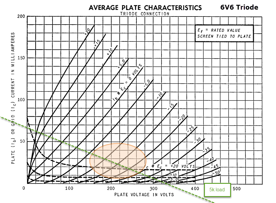
We can choose to bias the tube anywhere along this line. We already mentioned how nice and even the spacing is around the -15V grid line, so let’s choose the intersection of the 5k load and the -15V grid line. That corresponds to 25mA of current through the tube.

The cathode resistor is simply 15V / .025A = 600 ohms. The nearest standard resistor value is 620 ohms and that’s close enough for tubes. This is how you set an operating point. Congratulations! If you’d like to use something other than a 6V6, just follow the same basic steps.
We want the preamp to be able to drive a 10k input impedance on an amp without losses in frequency response. If we set the -3dB cutoff to 10hz, we’ll need a cap of at least:
1,000,000 / (2 * π * 10 * 10,000) = 1.5 uF
Round it up to 2.2uF because it’s a standard value. Output impedance is about 1,200 ohm so the signal loss into 10,000 ohms is less than 1dB. This would be worst case scenario; many amps have a higher input impedance.
Power supply
Now that we have set a load value and operating point, we can determine the voltage we’ll need from the power supply. In this case with a resistor loaded grounded cathode amplifier, the power supply voltage is just the x intercept of the loadline. It looks like it’s about 330V.
There are a thousand and one ways to get 330V. We’re using big tubes in this preamp, so I’m going to add a couple more. The first is a 5U4G rectifier (also available in sexy ST shape bottles). The second tube is a 6L6GC configured as a feed-forward shunt regulator. This doesn’t provide tight DC regulation, but the arrangement (in theory) cancels ripple from the power supply.
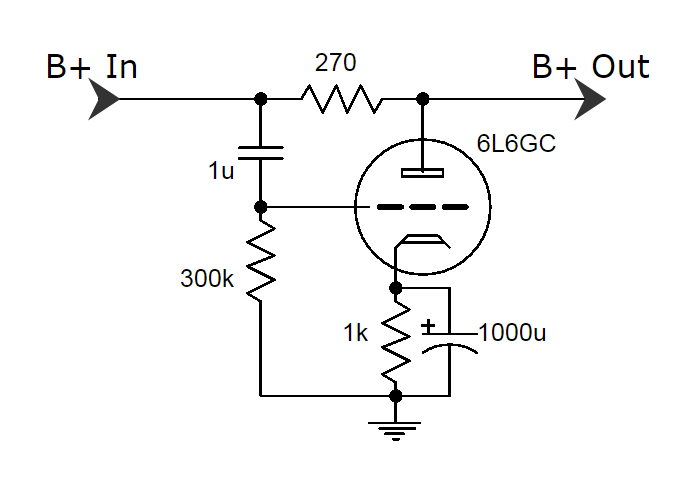
Any ripple from the power supply enters the grid through the 1uF cap connected between grid and B+. The tube, arranged as a grounded cathode amplifier, amplifies the inverse of the ripple seen at the grid across the series resistor (270 ohms). The key is the tube’s transconductance (eg X mA/V) and how this affects current through the resistor.
Each volt of ripple will cause X mA of current change (inverted). If we size the series resistor as the inverse of the transconductance of the tube, we put XmA through 1/X ohms. Current through a resistance creates a voltage (Ohm’s Law). We have an equal (X / X) but inverted amount of ripple voltage across the series resistor, cancelling out the original ripple from the power supply.
The power transformer secondary voltage shown (750VCT) was a choice based on opportunity and thriftiness (Allied 6K7VG). The 1k25 resistor helps us drop enough voltage after taking into account the current through the shunt (about 30mA) and the audio channels (25mA each). It is dropping about 100V at 0.08A, or 8W dissipation, so I used four 5,000 ohm 10W resistors in parallel. Big tubes, big parts. You can use a lower voltage secondary and smaller CRC or CLC filter if you feed the shunt section about 350V.
Schematic and BOM
Here’s what our parts look like in the circuit.

Click here for the bill of materials in PDF (missing a 220k 2W resistor for cap bleeder)
Construction
Click here for a gallery of progress shots
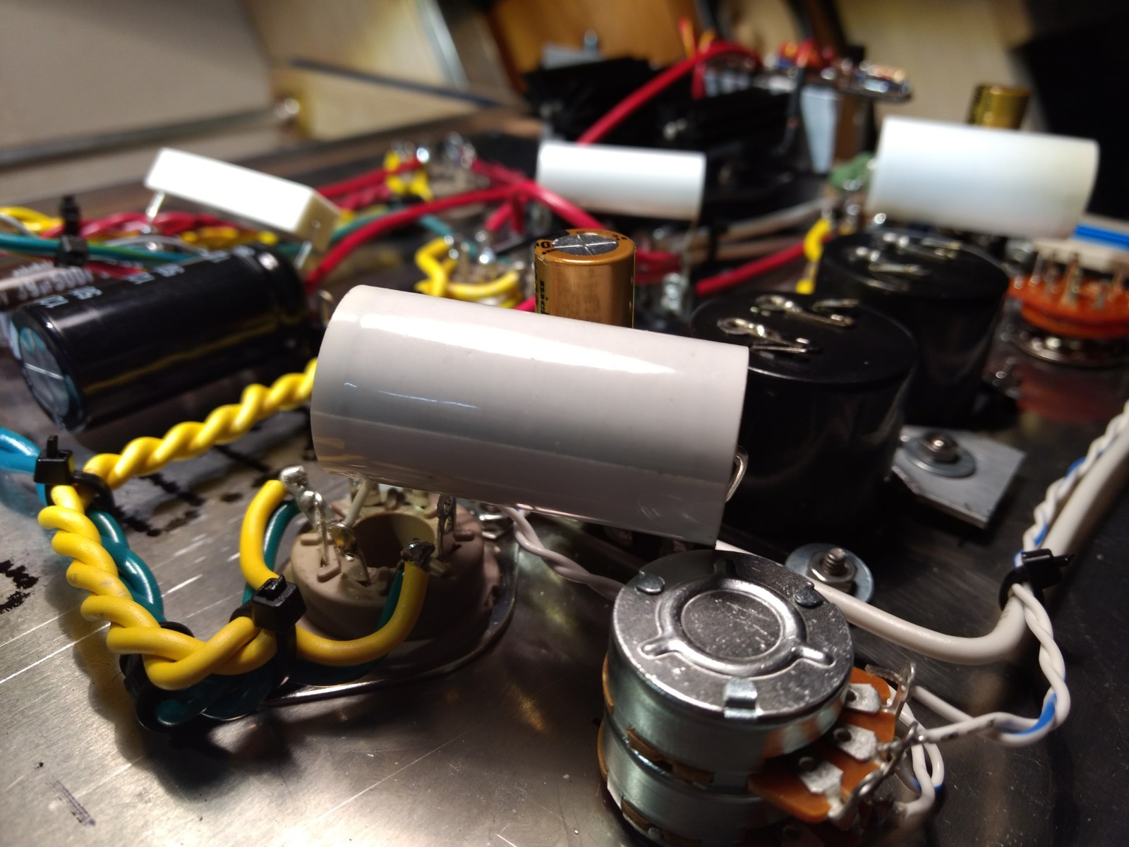
Note: 6V6s are known to be microphonic in this kind of arrangement and my build was no different. Using rubber grommets to mechanically decouple the sockets from the top plate, or tube damper rings might help. Listening to music (even at very loud levels), microphonics were not an issue.
Also check out this Imgur build gallery by another DIY tube builder, Joshvito! He includes an awesome level of detail if you’re thinking about building one of these.
Thoughts
There is something wonderful about a single resistor-loaded gain stage. Give it a quiet power supply, and you’ll be rewarded with amplification that is as pure as can be built (in the sense that it passes through a minimum number of components). Because we used big tubes, it dovetails well into any system without having to worry about impedance matching.
This design could easily be modified with a CLC filter in the power supply in place of the feed-forward shunt. There are also a variety of tubes that would work well in the audio channels (Mu < 10, Rp < 2k). As someone that usually sticks to buffers and just-enough-gain-but-no-more when I build, I found the sound of a simple grounded cathode stage with a big tube to have something special going on.
If you need a little gain and flavor in your life, I recommend this very simple preamp.
