
Before you impale your brain meats on this section, you might want to take a look back at the loadline calculations page. A lot of this section will assume an understanding of what a loadline is and why. And I’m lazy as shit and don’t feel like rewriting stuff.
CCS stands for Constant Current Source. You can construct a CCS out of lots of different things, including tubes (usually pentodes), but solid state seems to have become the most popular CCS device due mostly to size and cost (read about a simple discrete BJT+LED CCS on this post). A CCS pretty much does what it says on the tin: it provides a constant source of DC current for/through a vacuum tube (or other device). To understand why anyone should give a damn, we have to talk a little bit about how a tube creates distortion.
Distortion
Distortion in a tube amplification device is a measurement of how the output differs from the input in terms of the waveform shape (not the size, which is a measure of amplification). Differences in the waveform shape are often the result of nonlinearities inherent to the amplification device; this is to say that real-world amplification devices do not amplify the same amount at every operating point or with every input signal level. I just made hot technical diarrhea all up in your lap and I apologize. Let’s look at a picture.
These plate curves are dirty AF:
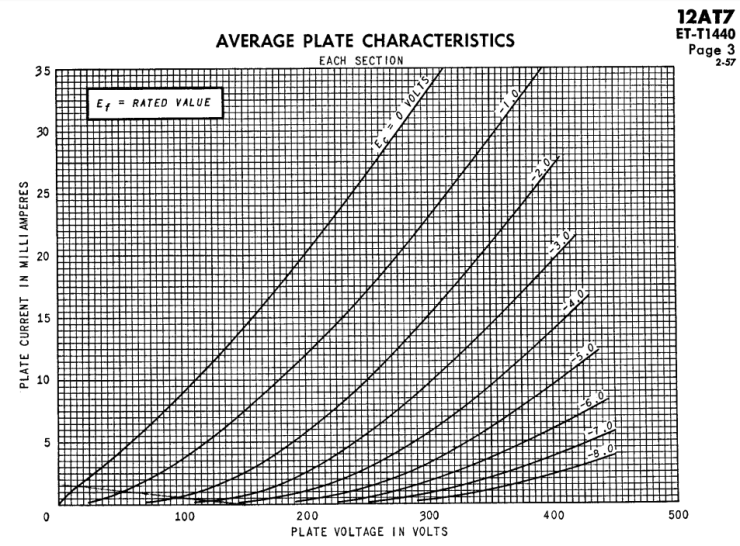
The input signal at the grid of a tube modulates the current through the tube, which develops a voltage across the load. That signal causes the tube to swing around the loadline from grid line to grid line. When the grid lines are not evenly spaced, like in this graph, that means that the amplification of the signal will be nonlinear. For example:
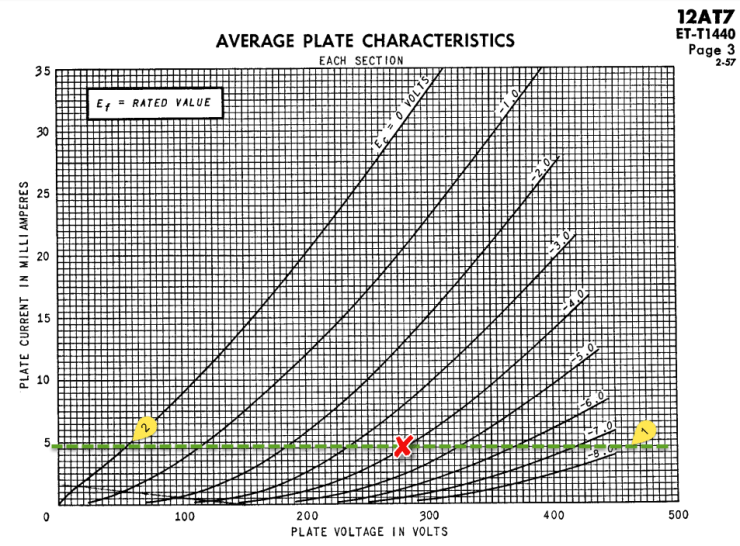
 In the above figure, the 12AT7 has a 400V B+, a 26k ohm load resistor, and an 800 ohm cathode resistor. The red ‘X’ is the operating point and the green line is the loadline. If the grid sees a signal large enough to cause it to swing between points 1 and 2, it will be distorted because the grid lines at point 1 are much closer together than at point 2. The spacing of the grid lines are an indication of the voltage amplification at any given point (amplification is the change in plate voltage divided by the change in grid voltage along the loadline). If the tube is amplifying one part of the signal more than another part, that’s no bueno.
So how can we minimize this distortion? The first answer would be to not choose such a dumbass operating point. That’s a valid answer and usually the first option to consider. But f@%k that because science. Now, consider what happens if we use a CCS instead of the 26k resistor as a load:
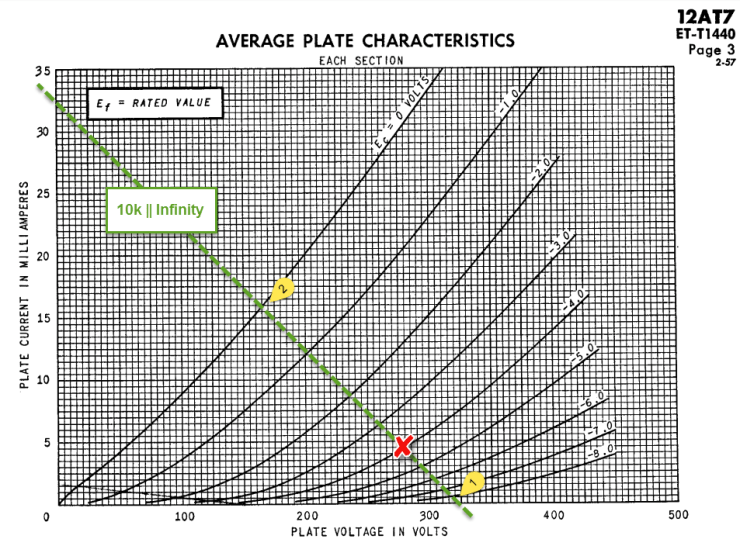
 Okay, that still isn’t perfect but it’s a hell of a lot better than before. The bias point (red ‘X’) is still in the same place (assuming the CCS as a plate load and the same 800 ohm cathode resistor) and the same signal as before will swing the plate between points 1 and 2. Now points 1 and 2 are much closer to equidistant from the bias point, the catch is that we would either need a higher B+ (around 575V) to swing all the way to point 1 or we would have to lower the bias slightly to put point 1 closer to the 400V B+ from the previous example. Let’s assume we have unlimited voltage (tits).
The CCS both sets the DC current through the tube and flattens out the loadline. It flattens the loadline because it presents an uber-high AC impedance (ie it resists changes in current because it’s a …CONSTANT CURRENT SOURCE).
A bigger AC picture
When considering a CCS though, we also need to take into account what we will connect it to. Impedances in parallel work like resistors in parallel and so that super awesome AC megaload can be ruined by the rest of the circuit. For example, if we capacitor-couple this CCS loaded 12AT7 to an amplifier with a 10,000 ohm input impedance, the AC load that the tube sees is now the CCS in parallel with the 10,000 ohms. If we assume that the CCS is perfect and presents an infinite AC impedance, the new AC load caused by the amplifier is 10,000 ohms and our loadline looks like this:
 The operating point is still in the same place because the CCS is still setting the 5 mA DC current, and the 800 ohm cathode resistor is still setting the grid bias, but in AC terms everything went to hell. We might be able to salvage some of this by choosing a different current and operating point, but first let’s consider what happens if the 12AT7 is connected to an amplifier with a 100,000 ohm input impedance:
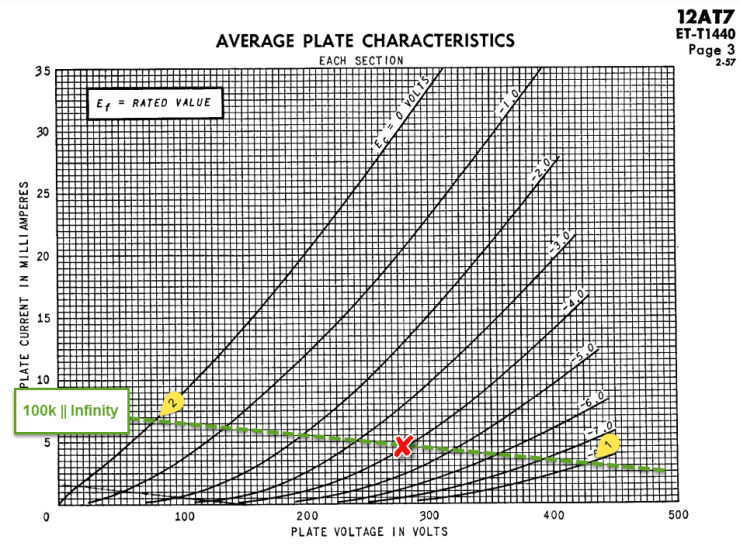
Hey, that doesn’t suck as much! The 100k input impedance from the amp in parallel with the infinite AC impedance of the CCS results in a 100k impedance for the tube. That makes a pretty flat loadline. This gets even better if instead of an amplifier, the tube is connected to another tube where the input impedance will be determined by the grid leak resistor (often 1,000,000 ohms, though other factors need to be taken into account, too).
A 100k load without the CCS to set the 5mA bias point would look more like this:
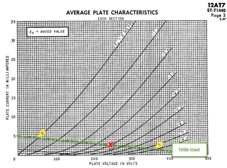
In this case, the 100k load and not the CCS is dictating where we can put the operating point and this results in significant line-squishing shenanigans and nonlinearity. It also means significantly lower voltage amplification. The CCS was a definite improvement.
So, a CCS comes in very handy when you want to set a bias point and it can also be a huge help to reduce distortion and increase voltage gain if the following parts of the circuit keep the AC load high. The most important aspects to keep in mind are the difference between setting a DC operating point and the AC loadline (which must factor in what everything is connected to).
See, solid state isn’t always bad.