
Phase splitters/inverters are used primarily in push-pull (AKA differential) amplification. In a push-pull amp, the output tubes’ inputs arrive 180 degrees out of phase. That is to say the inputs are ‘flipped’ in relative polarity. Think of them as two sine waves with one turned upside down.

Because the voltage signals at the grids of the output tubes travel in opposite directions, so do the anodes. While in single-ended amplifiers one end of the output transformer is fixed in AC terms, in push-pull amplifiers both ends of the output transformer swing simultaneously, creating (potentially) larger voltage differences and moar powar.
So, how do we get these equal but opposite phases? You can do so with transformers (see the Bad Hombre headphone amplifier), but that gets expensive, especially as the signals get large or if asking the interstage transformer to handle DC current. The most common option is to use tubes to split or invert the signal. There are several approaches, all having relative advantages and disadvantages. Here’s a brief overview of some of the common arrangements.
The Cathodyne AKA Concertina
A grounded cathode amplifier inverts the signal it sees. A cathode follower does not. You see, when a follower and an amplifier love each other very much, they do special hugs. Then nine months later, the tube stork brings them a cathodyne, which is a combination of both. The cathodyne has two outputs and one of them inverts while the other does not.

Although the unbalanced output impedance of a cathode follower is much lower than the unbalanced output impedance of a grounded cathode amplifier, if both the anode and cathode resistor of a cathodyne are equal, the balanced output impedance will also be equal. Please read this excerpt from Merlin Blencowe’s excellent book Designing High-Fidelity Valve Preamps.
A cathodyne is a very simple way of splitting phases, requiring only one tube and equal resistors (by the way, it also works with MOSFETs). Relatively limited headroom and slightly less than unity gain are the trade offs for this simplicity. With resistor loading, output signals cannot swing past the B+ or ground and the tube also drops a portion of the supply voltage.
The Paraphase
The paraphase looks a little crazy until you remember that grounded cathode amplifiers invert the signal. One output tube sees the same signal phase as the grid of the inverter, while the other output tube sees the inverted signal from the output of the inverter (the anode of the grounded cathode amplifier). The trick here is that the grounded cathode amplifier will have some gain, unbalancing the amplitude of the two phases (creating distortion). To overcome this, the input to the inverter is divided down by resistors (R7 and R8 in the diagram).
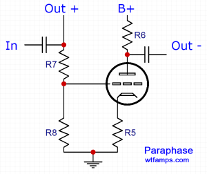
The paraphase preserves more headroom than the cathodyne and only requires an extra resistor or two. However, the output impedance and gain of the two phases will be difficult to match. This makes it rare in hifi circuits, but an interesting alternative for guitar amplification. This splitter configuration is complicated to direct couple and so it may limit negative feedback.
The Long Tail Pair
The long tail pair (LTP) has become a mainstay in push pull hifi applications. It preserves headroom, provides voltage gain, and has equal output impedance with one caveat: the tail must be long for good performance. The first triode in the circuit can be viewed as a grounded cathode amplifier, inverting the signal it sees at its input. The second triode in this arrangement, with its grid grounded, gets its signal from the cathode, meaning it does not invert the output at its anode. The shared cathode load is the ‘tail’ and is critical for good balance.

Generally, the higher the impedance of the tail, the better matched the gain and output impedance of the LTP splitter. Although we often use a CCS today, a large resistor and negative voltage rail can also work well. Where negative rails are not available, you eat up some of the headroom and/or sacrifice the balance. The biggest disadvantage of the LTP is that it requires an extra triode, negative rail, and/or CCS, making it relatively more complicated than other phase splitters.
