
Balanced vs Unbalanced

Balanced is a muddled topic out there in the headphone world, no doubt mostly due to audio marketing voodoo (ha, imagine that). “Balanced” and “unbalanced” are types of connections. Balanced and unbalanced are not types of amplifiers. They’re not different numbers of devices. They’re not different planes of existence. They’re just how one thingy gets its voltage signal to another thingy. That’s it.
A balanced connection implies that each phase (positive or negative voltage reference) of a signal has an equal impedance to ground (or some common point). An unbalanced connection has a single voltage reference (rather than two phases) and a reference to ground. Either can be accomplished with one or more amplifying devices. Transducers like speakers and components like amplifiers only care about the difference between the two references they see, whether they are two phases of a signal or a signal and a ground.
In high noise environments with tiny signals and long cables (like live sound), balanced is awesome because any noise injected into the cable is imprinted on both phases equally, so the difference between them doesn’t change. An unbalanced cable wouldn’t have the same advantage because the noise would not imprint itself equally on the ground and the signal. But if you use your headphone amp on your desk with a two meter cable and a DAC, the common mode rejection (CMR) of balanced signals means diddly.
Balanced and unbalanced are connections. That’s it. The rest of the balanced vs unbalanced clusterf&%kery is bad terminology and butthurt audio debates.
Differential vs Single-Ended
Single-ended amplifiers amplify the entire signal as a whole. Differential amplifiers (push-pull in common tube terms) amplify positive and negative phases of a signal separately; this requires more than one amplifying device, as well as a means of splitting a signal into phases (if it isn’t split already). Depending on how the output transformer is grounded, both single-ended and differential amplifiers can provide balanced or unbalanced output connection. In the same way, a transformer on the input of an amplifier can split or sum the phases of a signal for differential or single-ended amplification, respectively.
“So why is this amp differential?” you ask, your eyes wide and gleaming, your lips parted slightly as you lean forward in your swivel chair. “WHY IS THIS DIFFERENTIAL THEN?”
Firstly, small signal tubes, such as those with appropriate power and gain for transformer coupled headphone amplifiers, often come as dual triodes. As individual triodes, small signal tubes often do not have enough oomph to power headphones alone (though there are exceptions). In pairs, each half of a dual triode envelope amplifies its own share of the signal in a channel, making more power without having to step up to larger tubes or more amplification stages.
Secondly, push-pull transformers have a higher primary inductance than single-ended transformers of the same size and cost. More primary inductance (assuming equal tube output impedance) means more extended and cleaner bass response. Push-pull transformers have a higher inductance because they do not require an air gap to prevent current from saturating the transformer core. Current doesn’t saturate the core in push-pull transformers because with differential amplification it travels in equal but opposite directions (thus net current flow is zero).
Thirdly, differential amplification has superior power supply noise rejection to single-ended amplification. If there is power supply ripple, it appears on both phases equally. Just like with balanced connections (and CMR), the secondary of the output transformer only cares about the difference between the two phases across the primary. And so any ripple common to both phases is cancelled at the output. That means the power supply can probably be simpler and less expensive.
Lastly, small 8k:8 ohm push-pull transformers are literally everywhere because they’re the most common value for a pair of push-pull EL84s or 6V6s, two of the most popular power tubes ever made. If we want to make sure our amp will work with low impedance headphones, the same transformer would present a load of 32k with 32 ohms on the secondary. Because each tube in a differential design sees half of the primary turns, they also see one quarter of the impedance, or about 8k. Luckily, 8k is a pretty ok load for several small dual triodes.
Knowing these advantages, should you totally give up on single-ended amplification? Hell no. But we wouldn’t be tube nerds if we didn’t dabble a bit in various topologies to find out where theory meets reality. And that’s the story of why I decided to design a differential amplifier with balanced output.
Get off your soapbox and dance, monkey
Differential amplification is only as good as the balancing act it performs across phases. If we don’t have good balance, we don’t cancel the power supply ripple. We also end up with net DC current flow in the primary, so our inductance is lowered. And if one tube is amplifying a lot harder than the other, we’ll have lower power and increased distortion. So how do we provide the best balance between tubes?
Phasers set to split

If the input is unbalanced, the first thing we need to do is “split” the phases of the signal (turning one “upside down”). This can be done with tubes configured as phase inverters, or PI for short. The common configurations are the cathodyne (AKA concertina), long tail phase splitter, and paraphase. But because this amplifier is for headphones, I’d like to keep the overall size and power supply requirements low. So instead of a tube, we’ll use a small transformer to split phases.
The input transformer sees an input voltage across its primary. Through electromagnetic induction, any changing voltage (eg a signal) applied to the primary induces an electromagnetic force (EMF) in the secondary, creating a corresponding voltage on the output. The voltage swings symmetrically in the secondary and so at the outputs at each end of the secondary with the center tap grounded, we have two opposite phases of the signal. If you didn’t understand every facet of what I just wrote there, join the club (now there’s two of us). Transformers split good.
Edcor, my favorite place to buy beer-budget transformers, makes a series of affordable matching transformers. The WSM 10k:10k is a 1:1 (output level equals input level) matching transformer with center taps on the primary and secondary. We also used a WSM model transformer in the single-ended Papa Rusa parafeed headphone amplifier (which is a much more demanding circuit for this transformer).
Constance is the essence of quiescence
So for a differential amplifier, we have two devices amplifying. We want these two devices to conduct in equal and opposite directions with respect to the output transformer primary’s center tap. If we assume the two devices match (though IRL they never do perfectly), the sum of their equal but opposite conduction will be a fixed number. That fixed number will be the sum of the currents at the tubes’ operating points.
Imagine the two tubes’ loadlines. As one tube’s grid voltage is pushed positive, current through the tube increases because it is pushed up the loadline. At the same time, the other tube’s grid (which sees the opposite phase of the signal) will cause the tube to conduct more in the opposite direction:
The total DC current draw should therefor be constant, even though the tubes AC behavior follows the phases of the signal. The more fixed the current is, as in the higher impedance it shows to changes, the better balanced the signal behavior will also be. A shared resistor would be ok, but even better is a Constant Current Sink or CCS. As long as the tubes are reasonably matched, it’s a dead simple way to improve the performance of our differential stage.
There are plenty of ways to build a CCS: pentode tubes, BJTs and LEDs, MOSFETs, and so on. My favorite, because they are cheap, easy, and low parts count, are integrated chips (by the way, builders favor approaches that mirror their own personalities). Although its impedance could be bettered with more complicated circuits, nothing beats the LM317 voltage regulator turned CCS for simplicity and availability:
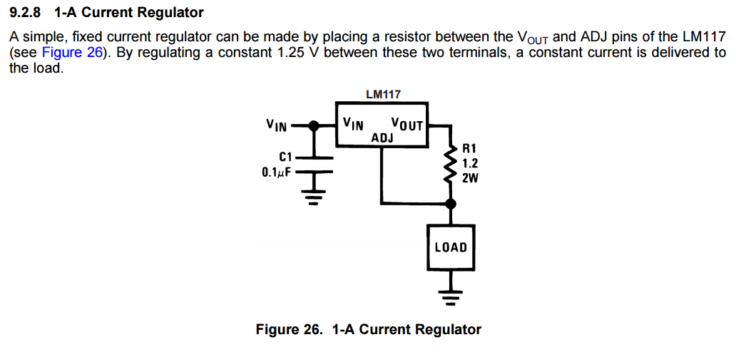
To calculate the value of R1 (which sets the current), just divide 1.25 V by your desired current. If we want 25mA, we need a resistor of 1.25V / .025A = 50 ohms. Easy peasy. Options abound for trying different CCS styles as well. This is not a high current application.
Tubes
Output Tubes
We’ll be using a transformer that provides an 8k load to each triode (with 32 ohm headphones), so we want tubes that have a plate resistance of 3k or less. Because we want to keep the size of the amp down, we also want dual triodes (one dual triode per channel). To be able to bias the tube to produce a reasonable amount of power, it should have a dissipation rating of at least 3W per triode. We like our tubes hot.
And finally, whatever tube we choose should be reasonably common so that replacements are not difficult to find (eliminating E182CC, otherwise a good candidate). This last detail leaves us with just a couple of choices: ECC99 or 5687. These tubes are similar enough that the same basic design would work for either, but keep in mind that the pinouts are not identical and would need to be changed if swapping.
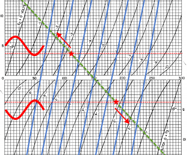
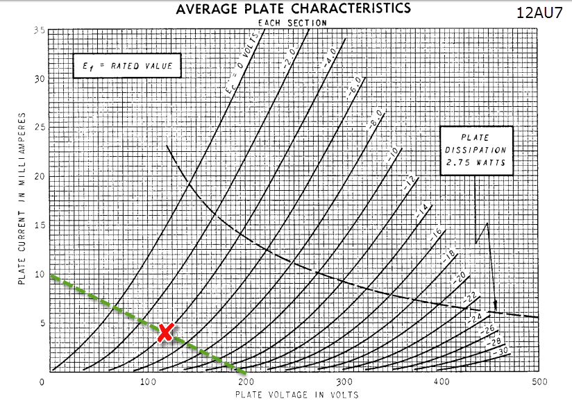
Loadlines
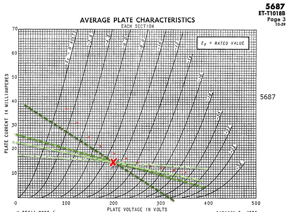
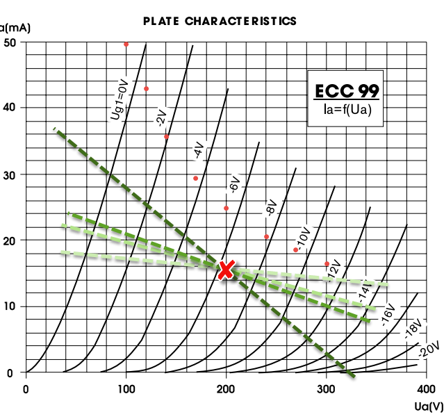
We can see from the loadlines that the tubes are biased at 12.5mA (5687) or 17.5mA (ECC99). That’s a total current through each channel’s CCS of 25mA (50 ohm resistor) or 35mA (35 ohm resistor), respectively. Because our output transformer determines the load, our B+ determines the anode voltage, and the CCS determines the current, our bias voltage is already set between about 7V and 9V, depending on the tube we use.
With a 2Vrms (5.7V peak to peak) input and a 32 ohm load on the secondary, a 5687 or an ECC99 would make about 125mW:
P = 2 * (Va – Vmin)^2 / (Zpri)
0.125W = 2* (200 – 155)^2 / (32,000)
That’s 20dB more than the headphone’s sensitivity rating at 1mW (95db+ for most headphones). With 300 ohm headphones, the load increases and power output decreases to about 20mW, or roughly a 13db increase over the 1mW sensitivity rating.* For most sane listening habits (80-90db), either is probably plenty.
*Note: See section on output transformers at the bottom of the page for OPT options with higher impedance headphones.
Look Ma, no caps
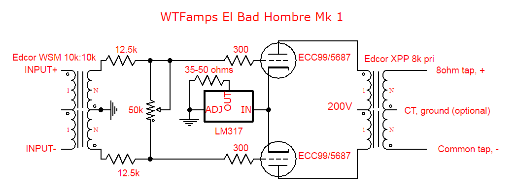
That’s one simple DIY amp and we don’t even need coupling caps. The volume control pot shunts the two phases together rather than sending signal to ground. If you add two equal but opposite things together, you get zero, so this shunt volume control is a nifty solution when you’re working with opposite phases. It is also inherently well-balanced as long as the two 12.5k resistors are well-matched. One dual gang pot is all that’s needed for two channels.
The secondary of the output transformer can be grounded at the common tap for unbalanced operation. You could alternatively ground the center tap for balanced operation. Wiring the two grounding options to a switch will let you compare them (hint: you won’t hear a difference). Although leaving the secondary floating for balanced output would be the technically ideal approach, there is some debate about the safety of a floating secondary on a tube output transformer. See additional notes at the bottom of the page on output transformers and secondary center taps.
| Part | Qty | Note |
| Transformers | ||
| Edcor WSM 10k:10k | 2 | 1:1 small signal transformer |
| Edcor XPP10 8k:8 | 2 | 8k:8 ohm push pull OPT |
| Antek AS-05T160 | 1 | 50VA, 160V power transformer (with 6.3V windings) |
| Triad C-7x | 1 | 10H, 270 ohm DCR, 90mA choke |
| Tubes | ||
| ECC99 or 5687 | 2 | Either (or both, wink) |
| Resistors | ||
| 12.5k ohm 1/4W | 4 | Get well-matched if possible |
| 300 ohm 1/4W | 4 | Grid stoppers |
| 35 or 50 ohm 1/4W | 2 | Sets current in LM317, experiment with values |
| 50k dual gang audio taper pot | 1 | Doesn’t have to be fancy |
| Capacitors | ||
| 220uF 300V+ | 2 | Power supply filter caps, 100-250uF range |
| Solid State | ||
| LM317 | 2 | CCS, no heatsink necessary |
| UF5408 | 4 | Rectifier diodes, fancier stuff is fine, too |
| I/O | ||
| RCA Jack | 2 | One red, one white |
| TRS Jack | 1 | Headphone output |
| IEC inlet | 1 | AC power input |
| Fuse holder | 1 | With a 500mA fuse |
| Power Switch (DPST) | 1 | On/Off |
| 9 pin sockets | 2 | Dem hold tubes |
| Other | ||
| Chassis | 1 | Put the amp in something |
| Terminal strips | Some | Or the wiring method of your choice |
Moar Powa!!1!?
Remember what I said about sane listening habits?
Additional Gain Stage Tube Choice
If you can’t stand the idea of only 115db listening levels, there is plenty of room left in the ECC99 or 5687 for more gain. Their grids are biased at about -8V and so they have room to swing 16V peak to peak before grid clipping occurs. If we want to be able to reach full output with a 0.5Vrms input (typical of phone outputs), we’ll want about 10-12x voltage gain. Just about every dual triode tube can do that, especially with a CCS.
Loadlines

These are examples of a 396A/2C51 and 12AU7 with a CCS set to 8mA (total), and a 20k load. Both have plenty of gain in this application and you should feel free to experiment with other driver tubes of around Mu 30 or less and Rp 7k or lower. Adding this extra gain stage to fully drive the ECC99 or 5687 would net about 1W of Class A power into 32 ohms, or an extra 10db over the 125mW version (remember that power and db have a logarithmic relationship). Increasing the B+ voltage and pushing the output tube into Class AB would further increase power as well.
In adding another gain stage to increase power you’ll give up some of the simplicity and lose the bragging rights of having a cap-less tube amp. Distortion at maximum levels will be higher due to the extra stage, but at comparable listening levels it won’t change much. I say build them both.
Yep, there’s a different CCS style in the Mk 2 version. Variety is the spice of life.

Power Supply
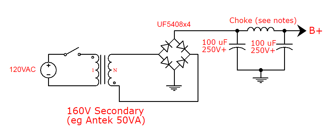
Either amp configuration above assumes approximately a 200V B+. There are many ways to get that, but here’s a simple supply. The choke does not have to be a high value, though its DCR should be 100-150 ohms. Something like the Triad C-14X would be about perfect. A choke will be better at reducing power supply ripple than a resistor, but if you absolutely cannot add any more (large and expensive) iron, use a resistor between 100-150 ohms (3W+ rated). The differential amplification should do a good job of cancelling ripple and you may find that the amp is perfectly quiet without the extra expense.
AC heaters should be fine provided you keep them tidy, twisted, and referenced to ground (through either a heater center tap or a virtual center tap).
Other notes on output transformers
I’ve received some questions about the output transformers, so I’ll elaborate a little bit. If you have high impedance headphones (150+ ohms), as well as low impedance headphones (32+ ohms), an output transformer with a 5k primary and 8 ohm secondary would be a good compromise for more power with the high impedance cans and acceptable distortion with the low impedance cans. If you have only high impedance headphones, an output transformer with about a 2k primary and 8 ohm secondary would work well (note this wouldn’t be recommended with 32 ohm headphones). The sticking point here is that it will be hard to find a transformer with a center tap on the secondary. We kind of lucked out that Edcor makes the affordable 7k6:8 transformer with the center tap.
We want to ground the secondary in some way for safety. I have read reports that a secondary can be capacitively charged up to a high voltage if left ungrounded. I haven’t personally experienced this, but we don’t eff around. Technically, to keep the output balanced, the secondary should only be grounded at its exact AC center (though if you read this whole page, you might realize that balanced output isn’t all that marketing departments make it out to be). This ground is what the center tap is for. Stuart Yaniger (the man, the myth, the legend) recommended that instead of a center tap on the secondary, the same thing can be achieved with a well-matched high value resistor (100k+ 1W+) from each phase of the output to ground (kind of a virtual center tap). That will have a negligible effect on loading, maintain balanced AC, and makes complete sense to me. If you want to use an output transformer without the center tapped secondary, try this.

My homie BrokenTofu built a very nice example of the mk2 version.

Have fun. Be safe. Enjoy music.
