
Mu, Gm, and Rp are kind of like in 1999 when you thought “Man, I would totally do Britney Spears.” There are a lot of assumptions involved in that statement, not the least of which are based on idealized devices and perfect testing conditions. I mean, what is the makeup and wardrobe budget? Would this be an impromptu performance or choreographed and lip-synched? And is the act predestined, or is it contingent on you randomly meeting said pop icon and like, you know, sealing the deal yourself? Basically I’m saying that the tube characteristics you read on a data sheet or calculate based on curves are imaginary, like your relationship with circa 1999 Britney Spears. But it doesn’t mean you can’t have fun “thinking about it.”

Mu
Mu is the AC gain of a tube with the plate current held constant. In a perfect tube, mu would always be the same. In real life tubes (which are bitches), mu varies based on your operating point, how much signal you feed the grid, and whether or not the tube was dropped on its head when it was a baby. Generally, more mu means more gain. Mu differs from a datasheet’s quoted amplification factor in that the amplification factor is given based on a set of conditions, while mu is just a number that represents the ratio of change in plate voltage to change in grid voltage.

You can estimate mu from a triode curve by calculating how much the plate voltage changes while holding the current constant and dividing this by the corresponding change in grid voltage. For example, at point #1 the plate voltage is about 170V and the grid is at -4V. If the grid moves 2V positive, to -2V at point #2, the plate voltage is now about 130V. If the grid moves 2V negative from point #1, to -6V at point #3, the plate voltage is now about 205V.
Change in plate voltage = 205V – 130V = 75V
Change in grid voltage = -2V – -6V = 4V
75V/4V = 18.75
So, for every 1V change in grid voltage, we are getting a change in plate voltage of about 18-19V. Let’s round it up and call mu 19 for this tube.
Gm
Gm is the transconductance of a tube. It is also often referred to as the mutual conductance. Probably neither of these terms mean shit to you, but that’s ok. Roughly, the gm of a tube is a measure of how much the current through the tube changes with respect to changes in the input voltage, holding plate voltage constant. That’s like a fancy way of saying how strong the effect of the grid’s voltage is on the current flowing through the tube. A tube with a strong grid has higher transconductance because input voltages make a bigger difference in current flow.
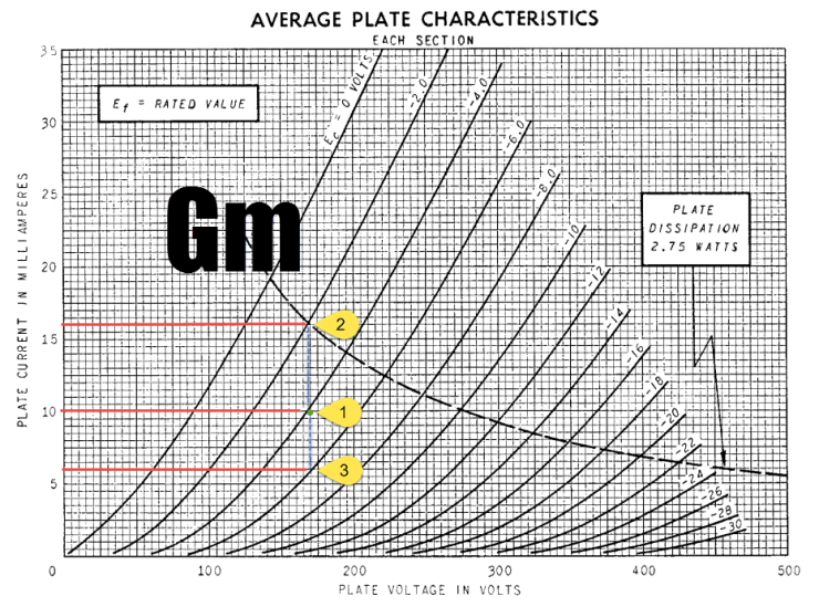
Like mu, we can estimate gm using a tube curve chart by calculating how much the current through the tube changes with varying grid voltage, holding plate voltage constant. At point #1, the current through our tube is about 10mA and the voltage on the grid is -4V. If the grid swings 2V positive to -2V at point #2, the current through the tube becomes 16mA. If the grid swings 2V negative from point #1, to -6V at point #3, the current becomes 6mA.
Change in plate current = 16mA – 6mA = 10mA
Change in grid voltage = -2V – -6V = 4V
.01A / 4V = 2.5 mA/V
Transconductance is measured in amps per volt, or siemens (pronounced exactly how you think it is, no snickering). Because we are dealing with milliamps in this example, we are talking about millisiemens. So the gm of this tube is about 2.5 millisiemens (tee hee).
Rp
Rp is the plate resistance of a tube. When you know the value of your load resistor and cathode resistor though, the plate resistance of your tube is very useful in ballparking your output impedance. We’ll talk more about output impedance in other sections, but just keep in mind for now that it’s an important characteristic to know when building most audio devices.
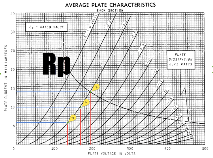
Rp can be estimated from a chart of tube curves, just like mu and gm. This time, instead of holding plate voltage or current constant, we’re holding the grid voltage constant and finding the change in plate voltage with respect to change in plate current. Yeah. Crazy. So at point #1, our grid voltage is -4V, our plate voltage is about 170V, and our plate current is 10mA. If we look at another point along the same grid voltage, like point #2, we find that the plate voltage is 195V and the current is 14mA. Going in the other direction along the -4V grid line to point #3, because why not, we find that the plate voltage is 135V and the current is 6mA.
Change in plate voltage = 195V – 135V = 60V
Change in plate current = 14mA – 6mA = 8mA
R = V / I
60V / .008A = 7500 ohms
Calculus or magic?
If you’ve been paying attention, you’ve noticed that in estimating the tube characteristics mu, gm, and rp, we’ve been using the same three variables the whole time: plate voltage, plate current, and grid voltage. Each time we define one characteristic, based on the interaction of two of the variables, we hold the third variable constant. You’ll also notice that what we’re trying to estimate with the calculations is the relationship of the change in one variable based on the change in another variable. If you haven’t run screaming from the room in some kind of math-triggered murderous enrampagement, it’s probably because partial derivatives don’t scare you. And that’s good. Because here is where this is all headed:
Mu = Gm * Rp
From above calculations:
18.75 = .0025 * 7500
Which looks a lot like:
V = I * R
KNOWLEDGESPLOSION! Yes, the three tube characteristics are all part of the same equation. If you’re a calculus nerd, and you already knew that, please drop me an email and I’ll be glad to slap you in the fecking mouth for ruining the surprise.
