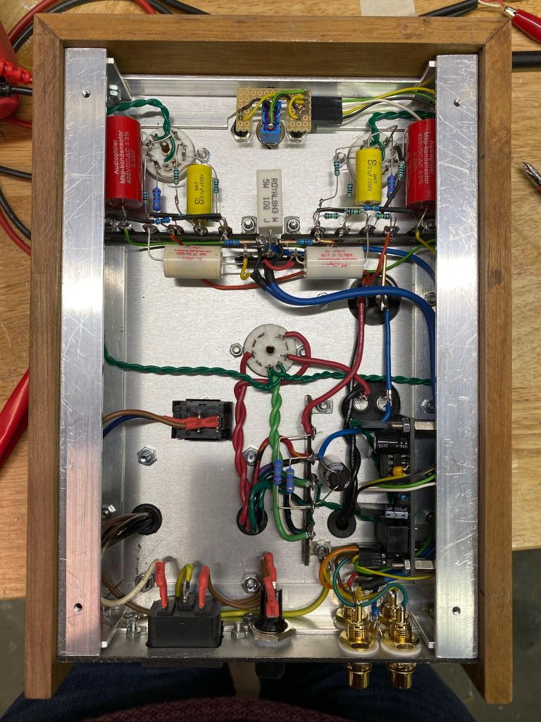
HM in the Netherlands shared a beautiful Muchedumbre XL build with me recently. He adapted his build to use a pair of Telefunken ECC83s (jealous). My notes on tweaks from our emails:
“In the Muchedumbre XL, adapting for different tubes is not so difficult (compared to resistor loads). A tweak to optimize for a 12AX7 in this circuit would be to lower the Rseries value a bit (1k5 in the original schematic). For a 12AX7, a value closer to 1k is optimal but this also depends on the amplifier you’re driving. I would not say this value is too critical unless you have a very low input impedance on your amplifier. The other value to tweak is the cathode resistor (300 in the schematic for 12AU7). A 12AX7 may be happier with a higher value here. Something around 1k-1k5 gives you more signal swing before grid current which is generally a good thing.”
He also includes a 45 second bypass relay based on the NE555 to save his powered speakers on power on and off.
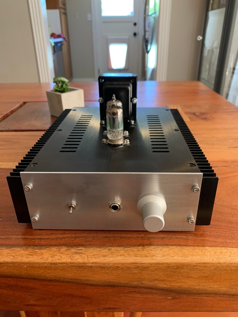
Reader CF sent me some pics of a gorgeous Papa Rusa build he recently finished:
I love the sleek case with functional heatsinks for the 5C45’s anode CCSs. It is a pretty compact build, judging from the proportions. CF used red LEDs to bias up the tube cathodes, too, and reports back that they sound great. Sweet build that I hope makes lots of great music for a long time to come.
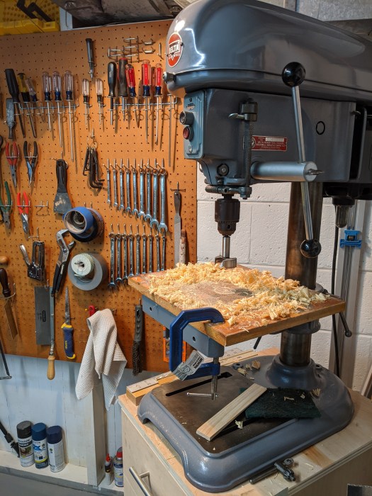
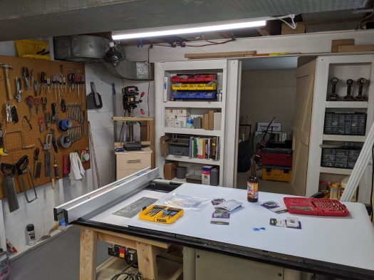
I also recently got a new toy of my own for the shop:
This 14″ swing Delta (circa 1950s?) replaces a much more recent 10″ Craftsman drill press. The Craftsman had a lot of projects under its belt, but I’ve been wanting just a bit more swing and a longer quill travel for a while now. The extra reach will be a help with larger top plates and the extra travel means I’m not moving the table so frequently as I switch from twist bits to hole saws and forstner bits.
With just some setup and test cuts so far, I’m loving this older machine. Everything is made of metal and on a nice beefy lever or set screw (of course that means it’s also heavy AF). Recently rebuilding the shop was a great excuse to finally pull the trigger on a sweet vintage press. Now it just needs a modern table and fence…
Not that I’ve had any shortage of projects lately, but they’ve all been workshop or home related. Now that the workshop is “done,” I’ve finally found a little time to return to tubes.
Many blogs ago, I posted about using switch mode power supplies (SMPS) in multiples to provide B+ for more typical tube operating points. That’s ‘typical’ as in 300V+, not the 48V of El Estudiante or other similar low voltage designs. I don’t see anything wrong with low voltage if it sounds good and meets a design goal, but it does hinder the tube and topology options.
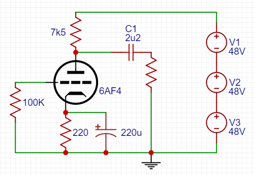
A few posts later, and still stuck on the stacked SMPS idea, I proposed a tube that might do well as a linestage with only 100-150V B+. The 6AF4 is a 7-pin triode with a modest Mu and low enough plate resistance to drive amps with a 20kohm+ input impedance without the assistance of transformers or followers. In short, it could make a really simple preamp with a really simple power supply for a really modest cost.
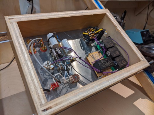
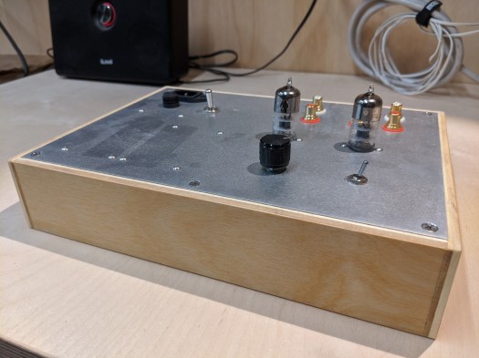
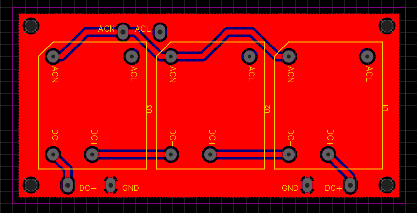
And that’s what I did:
The power supplies V1-V3 are XP Power VCE05 48V modules on a small PCB with some small capacitance filtering on the output (10uF). The heater supply for the tubes (one per channel) is a small 12V Meanwell IRM-05-12. Total cost as of this post is about $45. Current cost on a Hammond 269BX (300V CT) is $55 and you’d still need to rectify and filter to make a workable supply.
With the low parts count, sleeper tube, and inexpensive (and simple) power supply, this is a great cheap and cheerful project. It also sounds quite nice in use so far. I’ll update with a more complete write up including operating points, construction tips, and listening impressions soon!
I took delivery of a few 5×5 sheets of Baltic Birch and assorted hardware a few weeks ago and just completed construction of my dual workbenches. I’m a happy DIYer.
Why two workbenches?
My back and neck are happiest when I can sit at a workbench with the amplifier easel raising and angling a chassis so that I’m not leaning out over a project or having to reach too far. At the same, having space below a work surface for a stool reduces the amount of reinforcing structure you can practically include.
On the other hand, I need a sturdy bench for pounding, sanding, planing, sawing, etc. This requires a thick bench top or a frame that includes an apron running along the outside edges as well as stretchers tying the legs together. These extra structural bits impede on feet and space that could be used for rolling storage.
After trying to solve this trade-off for a while with differing designs of a single workbench, I gave up and just built two workbenches instead.
Both workbenches are along a ~10ft wall and just under 5ft long so that I could leave a gap between them to fit clamps, cords, etc. They are both 25″ deep and 36.5″ high and the rear edges rest on a horizontal ledger board lag bolted into the studs. They are made almost exclusively of Baltic Birch plywood and lots of Titebond.
The right workbench in the photo above is built with electronics and finer assembly work in mind. You can already see my amplifier easel in place, mounted on aluminum dowel so that it can swing up against the wall and free up the bench top. I have some common tools and wire already on the wall, but organization will be constantly evolving.
The electronics workbench is a double thickness plywood top mounted on some very beefy steel brackets from Rockler. The brackets are lag bolted into studs and I’m very comfortable with this setup for electronics and assembly. Best of all, I have maximum space underneath the bench for rolling storage, seating, feet, etc.
The left workbench is built with hand tools in mind. I loosely followed Paul Sellers’ plywood workbench design with laminated plywood legs and a tall front apron to resist racking. Unlike his workbench, I mounted mine on a ledger board in the rear, partly to keep it level with the sister bench and partly so that I could make use of the corner otherwise occupied by a sump system.
The hand tool workbench is secured to the back wall and ledger with steel angles so that I can remove it if ever needing to service the sump or change the room’s configuration. It will also have a vise mounted to the front right corner (on order). I’m happy with how immovable this bench is so far and plan to outfit it with some dog holes, etc over time. I haven’t decided yet how to make use of the wall space above the bench.
The rest of the room
Storage and drilling areas
The room is divided by my table saw which does double duty as an assembly table and a place to put a beer (love this cool magnetic vinyl sheet to protect the top). You can also see my rolling router table under one wing of the saw. Beyond the saw at the wall opposite my workbenches, I have organization for parts and materials and a corner for my drill press.
I still need to come up with a storage solution for tubes. They are presently in a plastic drawer unit which is fine but getting old and starting to fall apart. There’s some potential space in the shelving areas or maybe a rolling cart with drawers that could stow under the electronics workbench. I’m still waiting for inspiration.
My old Craftsman 10″ swing drill press is happy on the rolling cart of drawers, but a upgrade is high up on my list of tool priorities. It works nicely in the corner though, so a floor-standing press may be too tight with the height restriction.
There’s work left to do as far as organizing and fitting in all my stuff and I’ll continue to post on shop doodads and projects, but this blog will return to actual tube projects shortly! I finally have a functional (and much improved) workshop again.
I’ve had a few 6CB5As kicking around for a while waiting for a project. The 6CB5A has been documented by Thomas Mayer and Ale Moglia, among others, as a great option for triode strapping. Thing is, I like trying new things when I build and repeating a cap coupled formula for a two stage single-ended amp just wasn’t making it to my short list of projects (which I don’t quite have time for anyways).
A recent discussion reminded me of an idea to use the shunt cascode topology to direct couple to a single-ended output. It required some extra power supply rails, including a fairly large negative rail. These requirements aren’t anything too unusual; you see them with Morgan Jone’s Crystal Palace amplifier or any kind of fixed bias scheme (in a way).
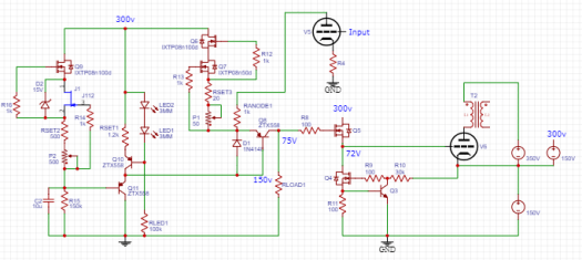
Anyways, the more recent discussion reminded me of a thread discussing a novel way of direct coupling two stages by stacking the power supplies. This is kind of similar to the Free Lunch AKA Monkey on a Stick arrangement. Applying this idea to my original shunt cascode brainstorm lead me to this:
We have a shunt cascode input stage. The output resistor (R2) idles at about 75V across it. This feeds a MOSFET source follower, which will have just a couple volts less on its output. So we have a very low impedance output at around 75V above ground and we want to direct couple that to the next stage. This is where I think it gets exciting.
We raise the cathode of the output stage so that it is positive relative to the grid (at 75V) by floating the output tube power supply (V2). The voltage we float it at is roughly equal to the target bias voltage plus half the target output swing. In other words, we raise it by twice the bias voltage for A1 or twice plus a bit for A2.
The output tube anode is connected normally and the cathode returns to the point where the output supply (V2) floats on the bias supply (V1). Our input stage is powered by another supply floating on the bias supply (V3). Our input and grid driving circuits are all referenced to ground and direct coupled. We can set the output bias by adjusting the current through R2.
Here’s a more fleshed out version:
It looks like a lot in the schematic, but I’ve already got shunt cascode and grid driver circuits on small PCBs. The power supplies don’t need to be anything exotic in this case as the input has decent PSRR already. The higher current output could use simple CLC filters as well.
Will I build it? I hope eventually. By summer I hope to have the workshop basically finished. I’m already enjoying having all the tools and parts in one (heated) space!
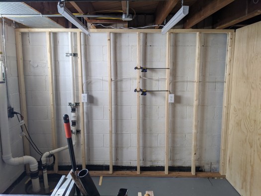
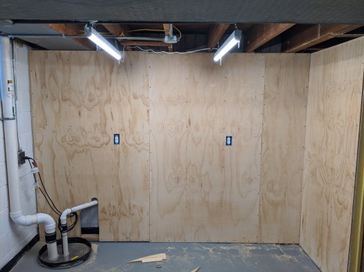
I’ve made more progress on the workshop room where my little tube hobby shop will soon live. Since the last post, I’ve ripped out a section of built-in shelving, framed the rear wall, had electrical installed, and covered said framed wall with 1/2″ plywood.
This plywood wall will eventually house a workbench for electronics and assembly as well as shelving (potentially a french-cleat type solution). The rest of the room is also taking shape with the addition of a small cart for my drill press and a section of peg board for hanging hand tools.
I still have plenty to do, but with a non-zero chance of a coronavirus quarantine, it’s very possible I’ll be spending more time in the tube bunker than expected. Next order of business is to build some drawers for the press stand and the workbench itself. When that is done, I’ll feel much more settled in the new space.
Lest anyone think I’ve abandoned the tube hobby, here’s some progress on getting the new workshop setup.
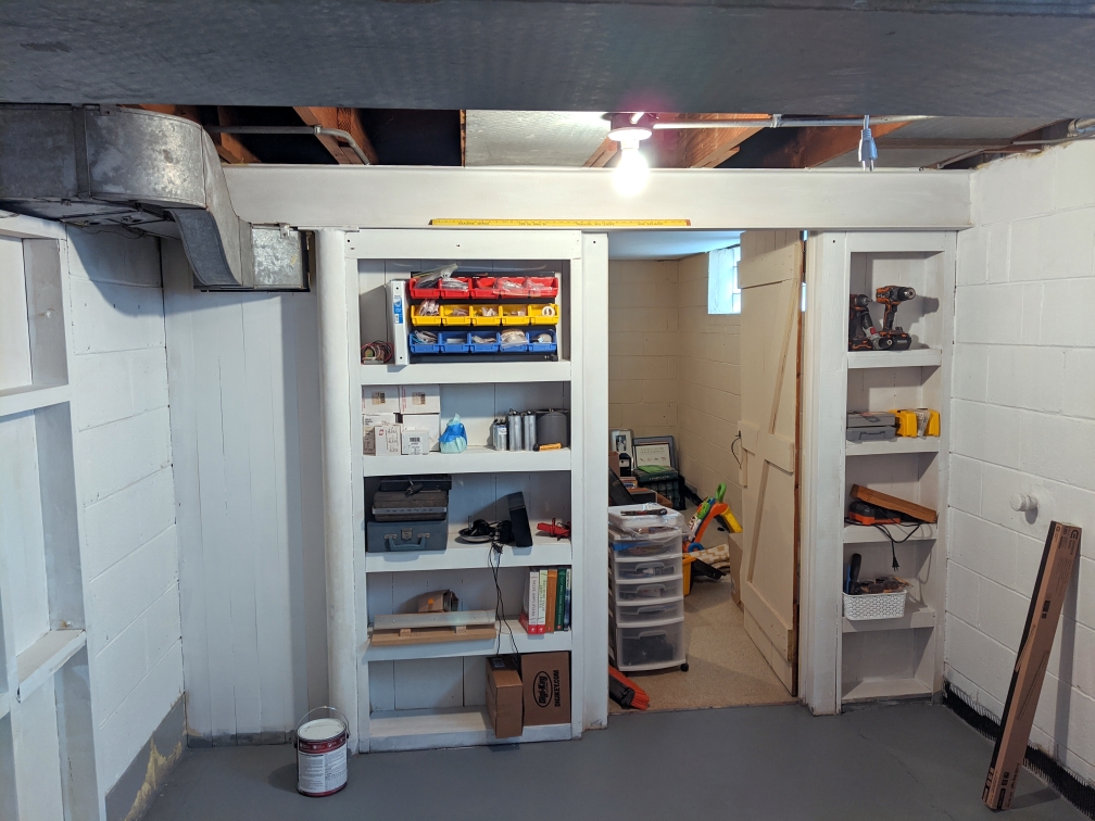
Here’s the before state of the workshop room (about 10ft x 15ft):
Some very interesting shades of yellow and beige going on in there. The perimeter had been excavated for a french drain before we purchased the house. Though other rooms in the basement had fresh paint and epoxy on the floor, this corner was pretty rough cosmetically.
First steps were to rip out some of the stuff hanging on the walls and ceiling. Then a deep cleaning, fresh Kilz on all wall surfaces and shelves, and finally a couple coats of floor epoxy to make sweeping up my messes (and finding dropped parts) easier. With the floor mopping and painting, it was stop-and-go work while things dried. I think that part is finally behind me.
Next steps will be to add more/better lighting, rip out the shelving perpendicular to the back wall (above), and frame it. I’ll add plywood over the framing to give me plenty of fixture options for tools and shelves. The workbench will also live along this wall so that I can reclaim some of the space in the sump and radon corner. This also lets me retain the full 10ft width of the shop in the rest of the space. That will be important for the woodworking tools.
The plan now is to have a single stationary electronics/assembly bench and everything else on casters so that I can configure the space for the given task at hand. Major woodworking tools in the room will be:
Miter saw station on cart with fold out supports
Drill press on cart with drawers
Router table, stows under electronics bench
Table saw, largish hybrid model (but I really wanted a cast iron top)
There’s big potential for saw dust in the small space, so I intend to add a dust collector eventually. This can live on the other side of one of the walls so that I can pipe a hose in when needed and save floor space. For the moment, I’m going to see how well a shop vac does with the relatively small pieces I usually work on.
Having recently moved and had a second kid, tubes should be the last thing on my mind, right? Maybe. Then again,personal hobbies should always have a place in day-to-day life, and especially when that life gets a little chaotic. Such hobbies are about exploration and continuously challenging oneself. And yes, sometimes a little bit of dorky obsession.
Hence, with all my tools in boxes and precious little spare time, I have a great opportunity to revisit quick, cheap, and cheerful tube design (at least this is what I tell myself).
Last spring I posted about a sleeper tube that looked to me like it had potential in a simple linestage. The single triode has modest B+ requirements, low Mu, and respectable transconductance, exactly what we might look for in a bare-bones capacitor coupled preamp. To boot, the tube is called 6AF4. AF. How could I resist?
Here are the plate curves, highlighted where it looks pretty good to me:
It looks like we could work with as low as a 100Vdc supply here, but plate resistance appears lower and more consistent if we have 150Vdc on tap. With 150V B+, a 7.5k loadline passes right through the middle of my target zone of operation, intersecting the y axis at 150V/7500 ohms = 20mA. A 220 ohm cathode resistor looks like a good place to start and should allow a dozen or so milliamps through the triode. The result, fleshed out, looks something like this:
Back in my original post on the topic, I mused about 48V switching supplies wired in series to generate a B+. That’s a monkey I still haven’t gotten off my back, so I drew up a little PCB based on the XP Power VCE05 module. This is a $12 encapsulated AC/DC converter that puts out 100mA+ at 48V. Three in series gives ~150V in a very compact footprint and at a cost comparable to a small Hammond EI transformer.
Although a pair of 6AF4s will only need 25mA or so, a pair of these boards would (hypothetically) be capable of powering a small power amplifier (300V @ 100mA). It’s worthy of some exploration.
Although all my parts and most of my tools are still in boxes, my household move is complete! It will still be a while before I’m spending free time in the workshop, but it’s never too early to daydream a bit about how I’ll set things up.
I have a blank slate of dry, mostly bare, concrete and studs/joists to work with. Aside from a sump in the corner, I’ll be able to utilize all 15ft x 10ft for my own storage and working space. Coming from space that was split between a garage and a shared basement, the 150 sqft is palatial. That said, my goal is to use it as efficiently as possible.
Amp Work Zones
Taking a cue from kitchen design, I’m planning the room layout by functional zones. Specifically, building tube amps involves three key processes: chassis work, electronics work, and parts/materials storage. Each process is a Russian nesting doll of other steps and tasks, of course, but these three general areas represent unique workflow challenges that are more or less shared by the sub-tasks that make them up.
Chassis Work
Messy in terms of generating dust, shavings, waste
Space has high potential to be used in non-hobby activities
The woodworking-focused area would benefit from mobility. Rooms adjacent to the workshop can be used as ad-hoc work space for projects that don’t fit in the smaller shop. Keeping tools and workbenches on casters will also let me rearrange as the work or materials require. Additionally, being able to moves benches helps with dust cleanup.
The old chassis work space
This will probably involve a 8ft+ bench for assembly with an integrated miter saw bay. Space under the bench will house a shop vac (dust control) and extra power tools and tool boxes. My drill press will live on a separate cart, as will my router table, for maximal flexibility.
I need to figure out a good way to deal with casters and the unevenness of basement floors.
Electronics Work
Benefits from flexibility in lighting and seated/standing work
Equipment is stationary and shelf size, but numerous
Results in many small parts used simultaneously
I’m planning to reuse the t-track chassis cradle I had in my last workbench. This was one of the best ‘tricks’ I picked up for building and working on projects. The rest of the space above the workbench will also be very valuable to keep power supplies, variacs, and equipment close at hand while working on a project. The worktop itself should have some kind of padding.
A project on the “easel”
This will likely also be about an 8ft long bench. I do not see a lot of benefit in making this a mobile bench due to its specialized nature and the manageable size of projects. Owning a CNC is one of my long-term hobby goals, so the extra long bench may come in handy (though it kind of breaks the ‘zone’ philosophy).
I’d like to come up with some kind of solution for keeping component parts organized while they’re out and being used for a build. This could be as simple as having tackle-box organizers on hand.
Parts and Materials Storage
Materials typically include long lumber and extrusions and plate under 18″ square
Component parts are numerous, but physically small and commodities
Tubes and transformers vary widely and some are fragile/valuable
The space has shelving built between studs that will help with storage for some things (mostly paint cans at the moment). Storing long materials high on the wall in a rack makes sense. Aluminum plate could be stored on edge without worrying about it deforming. The numerous component parts, tubes, and transformers, present an interesting challenge though.
In the past I’ve kept tubes in Rubbermaid drawers, but I’ve found that I’ll often forget about what I actually have on hand. Curing that will probably require some way of organizing tubes in a single layer, preferably vertically to conserve floor space. I have had my eye on french cleat style storage walls and am thinking about ways to adapt this to small parts and tubes. The modular nature of it has some potential benefits.
First things first
Before I start cutting too much wood for benches and storage, I plan to give the whole room a good scrubbing and a fresh coat of paint. Other rooms in the new basement have a coat of epoxy that I find to be very appealing, so I will likely treat the floor to make it easier to clean and generally more attractive. I’ll also switch out the bare bulb light fixtures to shop lights and have some additional outlets put in on their own circuit.
Yes, there’s lots to do in the new workshop! I plan on building a simple tube project or two in the meantime. Refreshing my memory of what it’s like to start out without a bunch of tools is probably a great exercise in and of itself!