

Design Goals
Everyone should own a single-ended triode amplifier at some point in their audio journey. Thing is, most audiophiles like to eat food and sleep indoors. Consequently, SETs built around DHTs and sperm whale oil impregnated coupling capacitors or transformers wound with rhinoceros butt hairs are not always within financial means. While I’m not the first person to seek an affordable SET with everyman parts, I am the first to include the phrase “rhinoceros butt hairs.” So please read on.
Output Stage
Single-ended triode amplifiers are inefficient. Loaded with an output transformer, the perfect output tube would be able to swing up to twice the supply voltage and down to 0V, but the tube would still dissipate power at the supply voltage and bias current. Real triodes made out of glass and metal instead of hope and rainbow farts are not able to swing close to 0V on the anode. That’s all to say that you can’t practically get more than single digit power output with SET amps (yes, there are impractical exceptions).
We’re only going to get a handful of watts, so only efficient speakers need apply (think Klipsch, Altec horns, and big full-range drivers, nearfield listening also works). One of my personal favorite tubes is the EL84. Not only has it been in production since the 50s, it was specifically intended as an audio amplification tube (originally for the Mullard 5-10 circuit). The EL84 is also known as the 6BQ5 and both the European and American designations are widely available.
While our output tube has a fairly low plate dissipation spec of 12W, it has a very respectable transconductance of 11 mA/V and is extremely easy to drive. This translates to a tube that sounds bigger than it actually is.
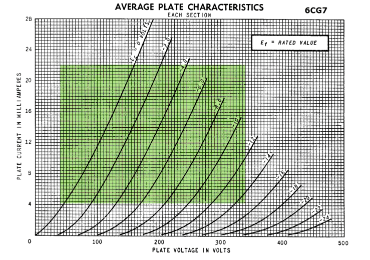
Here are the triode plate curves:
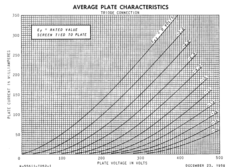
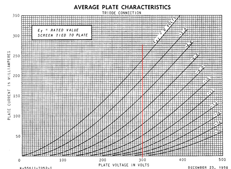
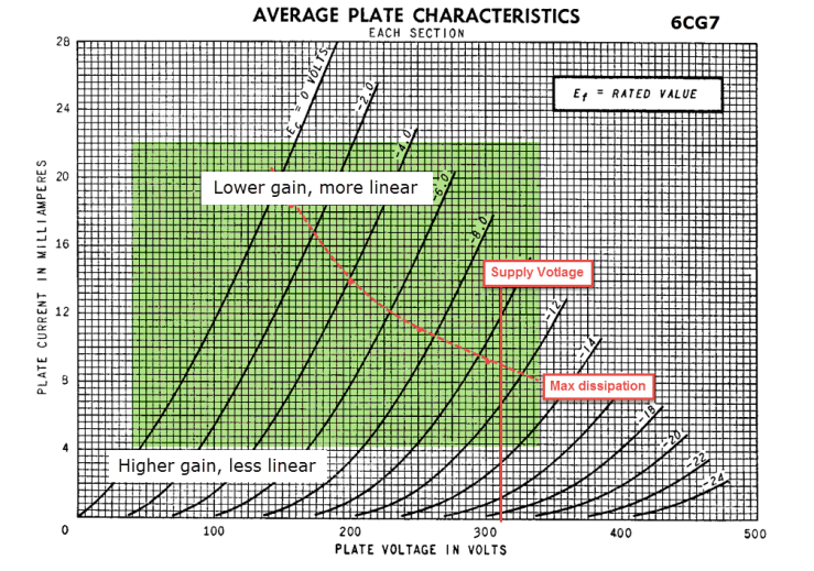
Although the scale of this graph makes things look a little wonky, we see some decently consistent spacing (indicating consistent Mu and/or Gm). Keep in mind the maximum anode voltage of 300V; we don’t have to worry too much about squish-ville on the right hand side of the graph. In order to extract maximum power from this mighty peanut, we’ll want to bias around the maximum anode voltage of 300V. Somewhere along this red line:
In addition to maximum plate voltage, we need to respect the maximum dissipation spec here. Most EL84 datasheets rate the plate dissipation at 12W but the GE 6BQ5 datasheet rates it as 14W combined between anode and screen. If we are triode-strapping the tube, the anode and screen are tied together. We could probably let the output tubes cook at 14W in triode mode and get an ok lifespan out of them, but our target current will be closer to the 12W rating to extend tube life. Calculating the current for 12W with 300V gives us 0.04A. Adding a line for our target current at bias point:
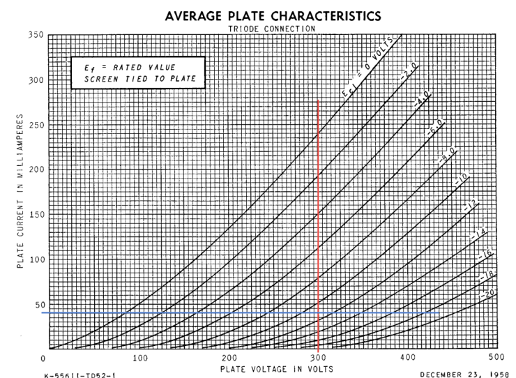
Now we’re smack dab at -11V on the grid at idle. We are going to cathode bias for this amp, meaning we aren’t applying -11V to the grid, we are raising the cathode by 11V and connecting the grid to ground. Consequently, the grid is -11V only if measured relative to the cathode. The grid isn’t negative at all. That’s right, get WOKE.
We know that current through the anode (our 40mA target) will also travel through the cathode resistor. In order to create an 11V drop with 40mA, we need a resistor value of 11V / 0.04A = 275 ohms (Ohm’s Law, natch). A value between 270 ohms and 330 ohms is in the right neighborhood (both of those are standard resistor values). This should be overrated for at least 2W (calculated dissipation is about 0.5W).
The output is loaded with a transformer and so the quiescent voltage is our supply voltage and the quiescent current is set with a resistor. If that all seems too easy, it’s because it is. The more ticklish part of output stage design is choosing the output transformer impedance. The impedance load is where we balance our goals of output power and linearity. Generally you’ll get more power with a lower impedance load and more linearity with a higher impedance load. Lucky for us, there are a finite number of transformer ratios that are easily available. We’ll look at three potential candidates: 2k5, 3k5, and 5k.
Our grid, biased at -11V, will swing between -22V and 0V. This will cause the anode to swing along the loadline by a much larger amount (in fact it is proportional to the tube’s Mu). The output transformer reflects this large anode swing to the load as a smaller voltage change, but a larger current change. If we assume there is no loss of power in the output transformer (spoiler alert: there’s a small loss), we don’t have to worry about the secondary or the turns ratio; we only have to look at the power produced on the transformer primary. In other words, we can calculate power output by looking at how much voltage change can occur at the anode for a given load impedance.
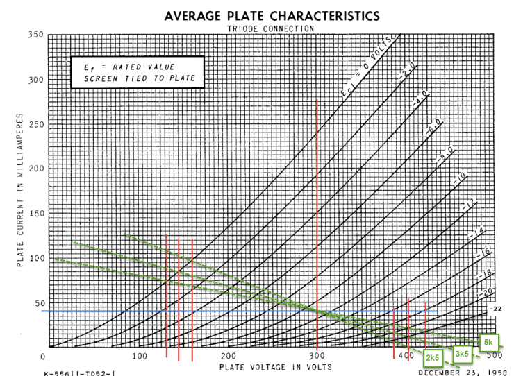
The green dashed lines in the above diagram represent loads. I draw/calcualte these slopes by multiplying 100mA (my y-intercept) by the load impedance and using the resulting voltage as the x-intercept. For example, using 100mA as the y-intercept and multiplying by 2,500 ohms, we get an x-intercept of 250V. Connect the two intercepts and you have a loadline. The last step is to move or redraw the line (maintaining the same slope) so that it intersects the bias point (here 300V at 40mA).
Finally, we’re at a point that we can calculate our output power. The 2k5 load looks like it allows the anode to swing between about 385V and 160V, a difference of 225V peak to peak. Our power output would therefore be approximately 2.5W:
Power RMS = Vptp² / 8*Z
225V² / 8*2500Ω = 2.5W
If we repeat the same calculations with the 3k5 loadline (about 255V peak to peak) and the 5k loadline (about 290V peak to peak), we get approximate output power of 2.3W and 2.1W respectively. Generally we get less distortion with a higher load value because the anode has closer to symmetric amplification “above” and “below” the bias point. The sound pressure level difference between 2.5W and 2.1W is less than 1db. In my opinion, it’s worth giving up a fraction of a watt for better linearity here. If all I had was a 3k5:8 transformer though, I would probably still use an EL84 (in fact, most datasheets spec 3k5 as the anode load). If all I had was a 2k5 transformer, I would probably pick another tube or put an 8 ohm speaker on the 4 ohm tap if the transformer had one.
The final note on output transformers is that using one with ultralinear taps will let you connect the EL84 screen in a way that will get you a little more power (4-5W) and still keep distortion to lower levels than full pentode mode. Ultralinear uses feedback from the transformer to the screen so that the output stage behaves like something halfway between a triode and a pentode in terms of power and distortion.
So yeah, that’s a single-ended output stage in a nutshell. You can repeat the same process with any triode. With larger tubes, you’ll find that you need to strike more of a fine balance between dissipation and maximum voltage ratings. We went right to the max voltage in the above example, but doing so with an EL34 (800V max) would be not only dangerous, but it would also leave you with very little bias current. With little current in the tube, you’d have little room for the anode to swing symmetrically with grid signal (ie, it would be down in the squishy plate curve muck).
And that’s all I have to say about that.
Input Stage
One of the advantages of the cheap and cheerful EL84 is that it doesn’t need a whole lot of gain from an input stage. With the grid biased at -11V, it will swing about 22V peak to peak for maximum output. A 1Vrms signal is already 2.8V peak to peak, so a voltage gain of less than 10x at the input stage gets us all we really need. It’s never a bad thing to have a bit extra, so something like 15-20x is a good target. Assuming a resistor loaded grounded cathode stage, we will need a tube with a Mu of 20-30 to get the target voltage gain after taking into account the effect of plate resistance.
We are already using a 9 pin output tube, so we may as well stick with the same socket for the input tube. Something about driving a 9 pin with an octal just makes me squeamish. We may as well also stick to 6.3V heaters. I’m leaning towards dual-triodes that are in current production (not that you have to), so the most obvious choices are 12AU7, 12BH7, 6DJ8, and 6CG7. While there is nothing wrong with any of these choices, the pedigree of the 6CG7 as electrically equivalent to the 6SN7 is what stole my heart. Just look at these borderline x-rated curves:

Our output stage is biased at 300V + 11V (remember that the cathode is raised by the grid bias voltage). I’ll round to 310V to make calculations easier. With a resistor-loaded stage, our supply voltage will be the x-intercept. It is the maximum voltage that can appear at the anode of the tube. Like a transformer, the anode resistor determines the slope of the loadline. Unlike a transformer, resistors do not store energy and so they don’t allow the anode to swing above the supply voltage. So, to find our y-intercept we will divide the supply voltage (x-intercept) by the resistor value to get the y-intercept; this is the current that would flow if only the resistor was connected between the supply voltage and ground.
Now, how do we find the resistor? I go through a few iterations to hone in on the ultimate value. The first step is identifying what part of the plate curves look pretty (straight and evenly spaced). For the 6CG7, I like this area:
But we also need to consider the maximum plate dissipation of 2.8W per triode (5.7W total if both triodes are used). With a supply voltage of 310V, operating at higher currents will require a fairly low resistor value, meaning less gain. Operating at lower current will allow more gain, but sacrifice some linearity.
Now, having determined about where I want the tube to bias, where it will blow up, and where the x-intercept must be, I draw some standard resistor values as loadlines (side note: nothing is worse than doing all your calculations for the perfect bias point only to find that the required resistor value doesn’t actually exist). To find the y-intercept, just divide the supply voltage (310V) by the resistor value. Here are load lines for a range of about 2x to 4x the plate resistance of the tube (6,600 ohms) using standard resistor values:

The voltage gain for these loadlines with a bypassed cathode resistor can be calculated as:
Gain = Mu * Rload / (Rload + Rp)
Gain w/ 15k ~ 14x
Gain w/ 20k ~ 15x
Gain w/ 27k ~ 16x
Any of the above is about the gain we’re looking for. The typical line level signal for home stereo products is 2Vrms or 5.6V peak to peak. Rounding up, a 6V peak to peak input signal would mean we need to bias the grid at least -3V relative to the cathode. This will allow it to swing between -6V and 0V. Using -3V as the target grid bias, we can calculate the bias current:
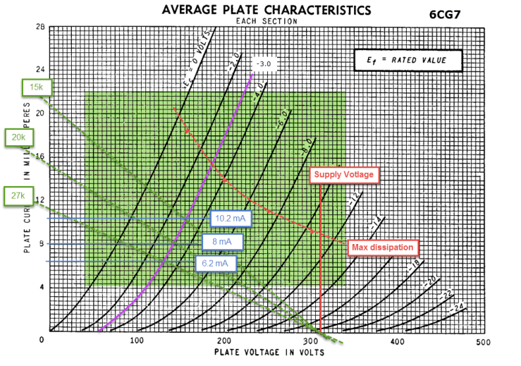
Any of the bias points should use an overrated 3W+ load resistor. The calculated cathode resistor varies between about 300 ohms (-3V / 10 ma) and 470 ohms (-3V / 6.2 mA). Choosing between the operating points might give the obsessive convulsions: they all provide sufficient gain and they all allow the 6CG7 to operate in the ‘nice’ region. My general approach is to use the largest plate load I can (highest gain) while still operating in an appealing region of the plate curves. In this case, that would be the 27k load resistor and 470 ohm cathode resistor. A little less current means lower demands on the power supply and a little less power/heat created in the chassis. Both are good additional excuses to just use resistors that I had on hand anyways (which is the best parts choice factor of all).
Reactance Checks (caps, caps, caps)
We have our bias points and resistor values roughly calculated for the two stages in this amp. Before we heat up our irons, we have a little bit of math left. In order to realize the calculated gain/power from our two stages, we need to bypass the cathode resistors. A capacitor is an AC short, so signals basically see a cathode resistor bypassed with a capacitor as ground. An unbypassed cathode resistor would reflect changes in current with signal as changes in voltage, meaning the grid-to-cathode bias voltage would not be constant. This is a form of feedback, and not necessarily a bad thing, but we want to preserve our gain/power in this amp so we’ll bypass the resistors.
The impedance of a capacitor to an AC signal depends on the frequency. The larger the capacitor value, the better it is at passing low frequencies. In this case, being better at passing low frequencies means little/no feedback at low frequencies and little/no loss of power. To calculate the capacitor value, we’ll use the following equation:
C in uF = 1,000,000 / (2 * Pi * Rk * hz)
The hz variable is the frequency at which we can tolerate a -3db loss in the cap’s effectiveness. I use a frequency of 5hz or less here. The Rk is our cathode resistor in question. The output stage has a cathode resistor of 270-330 ohms so we should use a bypass capacitor of at least 120uF. Our input stage has a cathode resistor of 300-470 ohms so we should use a bypass capacitor of at least 100uF. Rounding up in these cases is not a bad thing.
The other critical capacitor here is the one coupling the input stage to the output stage. This connects the 6CG7 anode to the junction of the EL84 grid and grid leak resistor (which is what gives the grid a reference to ground). We use the same equation for this calculation but we’ll get a much smaller value, which is good because we can use a higher quality film cap for this critical part. Using a grid leak resistor value of 470k for the EL84, we get a rounded up cap value of at least 0.1uF.
We do not have a coupling cap at the input of the amp normally because our sources should not have DC on their output. If they do or might, we can calculate an input cap with the same equation and a grid leak value of 1M for the 6CG7 (result 0.047uF or more). In cases where we have high gain or high output impedance in the input stage, or a large amount of Miller Effect capacitance in the output tube, we would do more calculations to be sure we aren’t losing higher frequencies. We don’t have those things here and this write up is already out of control, so don’t worry about it.
Power Supply Basic Requirements
Our B+ target is about 310V and we’ll need at least 100mA of total current (40mA per EL84 and 10mA per 6CG7 at hottest bias options). Our total heater current will be just over 2A, so we should look for 6.3V heater windings of 2.5A or more. These are all pretty modest ratings. I’m going to build my amp with tube rectification because I worry that the three little 9 pin tubes might get lonely. We could use a 9 pin EZ81 with 6.3V heaters and keep it simple. Of course I’m not doing that.
Of the big-bottom rectifiers, the biggest is the 5U4. Other than aesthetics, there is absolutely no reason it is necessary. But I think your amp should make you feel warm and fuzzy when you flip the power switch and watch the heaters slowly glow to life. Add some glass to your power supply not because it sounds better, but because it makes you feel good. You can do (legal) things just because they make you feel good, you know. I won’t stop you. Philosophy aside, the 5U4 needs a 5V 3A winding and will drop around 35-40V.
All this adds up to a power transformer with heater windings of 6.3V @ 2.5A+ and 5V @ 3A+, and a high voltage winding of about 550-600V @ 100mA center tapped after accounting for voltage losses in the rectifier and filter. Speaking of filters…
Filter Math
This is a low wattage amp, meaning we’ll be using it with high sensitivity speakers. That being the case, we should pay special attention to our power supply filter. Using a tube rectifier and capacitor-input supply, our 120hz ripple voltage will be fairly sizeable. Up to 20V peak to peak with a 30uF or so cap is possible. To knock this ripple down, we’ll use chokes and caps in a CLC filter.
Chokes resist AC (ie high impedance) and caps pass AC (ie low impedance). If we stick a choke and a cap in series and take the output from their junction, we build an AC voltage divider. Very little ripple appears across the lower leg of the divider (the cap) because it has very little AC impedance.

Our homes are fed either 50hz or 60hz AC power and so our full wave rectified ripple will be 100hz or 120hz. To determine the effectiveness of our filter, we can treat it as a simple divider where the fraction of ripple that the output sees is equal to:
Zcap / (Zcap + Zchoke)
Zcap in uF = 1,000,000 / (2 * Pi * 120hz * Capacitance)
Zchoke = 2 * Pi * 120hz * Inductance
We usually express the fraction in decibel terms just to make things more mathy. The above expressed as db would be:
20 * log ( Zcap / (Zcap + Zchoke))
This should give you a negative number with usual choke (1H+) and filter cap (100uF+) values. If you use more than one stage of filtering in series, you add the db reduction. Do yourself a favor and build a quick Excel spreadsheet for this thing (or use software). Based on parts availability and how much room I had in the chassis, I used the below filter for an 80db+ reduction in ripple. This equates to 10,000x less ripple than no filter and a very, very quiet amp.

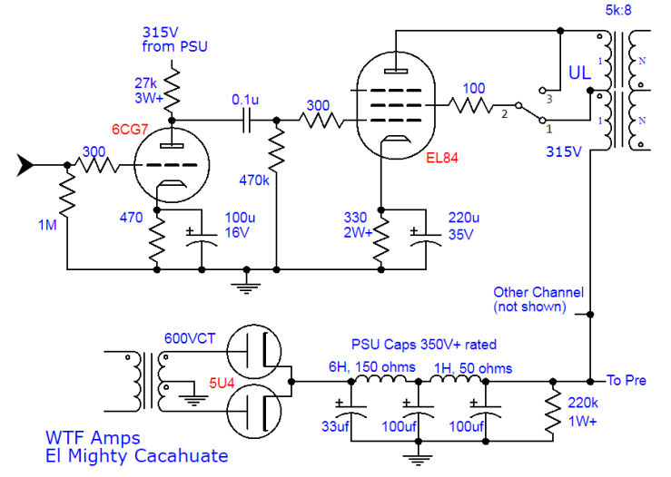
Schematic
Put it all together and what do you get? Ding dong, clap clap, stomp stomp, hot dog!
Click here for a Bill of Materials!
Pics


Other design notes
Cathode bypass cap
