

This pages involves advanced audio concepts/calculations that are not explained in every detail. If you don’t understand it all immediately, that’s OK. The schematic is at the bottom and you can certainly build it as shown. I highly recommend this paper on RIAA design, btw.
So you want to DIY a tube phono preamp. That’s cute. Unfortunately, phono preamp calculations are the most brain-bustingest thing you could want to design because of reactance. After you design it, a phono preamp is a PITA to build because the signals it handles are tiny and there’s all kinds of noise lurking around. The maths are gonna get cray and you’re going to have all kinds of crap to troubleshoot. If that doesn’t sound like fun, you’re perfectly sane. If it does sound like fun, I tip my soldering iron to you, m’lord.
Por qué tubes?
A good phono preamp should be designed around the following:
- enough “headroom” so that clicks and pops do not clip the gain devices
- low and/or unobjectionable distortion
- an accurate (or at least consistent) RIAA network
- low or no noise when in use in a system
- low output impedance for easy integration with other components
Tubes present inherent challenges to some of these factors:
- an accurate (or at least consistent) RIAA network
- low or no noise when in use in a system
- low output impedance for easy integration with other components
These obstacles can be overcome, but addressing them comes at the cost of complexity. On the other hand, tubes excel at the following:
- enough “headroom” so that clicks and pops do not clip the gain devices
- low and/or unobjectionable distortion
Tubes run at high voltage can be very linear voltage amplification devices. High voltage also generally means that designing for plenty of headroom is not a problem. What distortion is generated by tubes (within a safe overload region of operation) is generally monotonically decaying harmonics. In psychoacoustic studies listeners identify this as a “fuller,” not a distorted, sound. Read this excellent article that explores some of the reasons for the ‘tube sound’ (harmonic structure and intrinsic signal compression) in transducer-driven signals like microphones or phonograph cartridges.
The strengths of tubes when used in this application make trying to conquer their weaknesses an appealing quest. So, feck it. That’s porque. Also masochism.
Gimp-suit-pulp-fiction.jpg
An accurate RIAA network

Way back in the dark ages some monk or something found out that reducing the relative bass and boosting the treble helped cut better records. We’ve been cutting records that way ever since. This EQ adjustment is called the RIAA equalization and it has three transition points: 75 µs, 318 µs and 3180 µs (corresponding to 2122 Hz, 500 Hz and 50 Hz). There are many a dark art involved in devising such a network but we’re going to use this one:
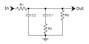
To hit the correct RIAA transition points from above, you want these equations to be true (all capacitors in uF):
R1*C1 = 2187
R1/R2 = 6.877
C1/C2 = 2.916
If you’re not already off somewhere cleaning out your pants, keep clenching that sphincter because to get the value of R1 we also need to worry about the effects of the grid leak resistor for the following stage (R0) and the output impedance of the preceding stage. Try these on for size:
R1” = R1′ || R0 …solved for R1’…
R1′ = (R1” * R0)/(R0 – R1”)
R1 = R1’ – Zout
The R1’’ is our calculated perfect value based on the three transition point equations. The R1’ is an intermediate variable. Our actual resistor value in the circuit (with respect to the grid leak and Zout) is R1. Ok, take a bathroom break.
Finally, for C2 we should consider the Miller Capacitance of the following stage:
C2 = C2’ – Cin
Where C2’ is the calculated value based on the transition equations, Cin is the input capacitance of the following stage, and C2 is the actual value of capacitor.
Cin = Cg-k + Cg-p * (stage gain + 1)
If you survive the math you’ll find that no one manufactures the values you want to buy and so you have to just get as close as possible with common resistor and capacitor sizes by putting them in series/parallel. So, yeah. More math.
A more consistent RIAA network
Tubes age with time and their performance slowly drifts. Because our RIAA calculations above rely, at least in part, on the output impedance of the tubes, the equalization will also change slightly. Each tube is a special snowflake and so simply swapping tubes is going to make a small difference as well. If we bypass the cathode, these differences are a function of the plate resistance (load held constant). Furthermore, if we choose smaller C values, the calculated R1 is relatively less dependent on the preceding stage’s output impedance and is thus less affected by drift. Tits.
The voltage coming out of your wall is another factor to consider when trying to keep the RIAA network consistent. It is not strange for this voltage to vary throughout the day and time of year. Unregulated supplies will feed the tubes a different voltage at different times and change their performance slightly. If we’re gonna get anal about consistency, we might as well regulate this little beast. There are many approaches, but none will give us as many pleasure-fizzies as voltage regulator tubes.
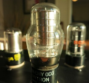
Voltage regulator (VR) tubes can be used as a simple shunt to provide the desired voltage to a load (though there are limits to the practical current draw). Basically, you connect your circuit in parallel to the VR tubes and the VR tubes induce current through a load resistor to keep the voltage constant at their anode. Think of them as zener diodes that don’t suck. They also look cool as heck.
Low noise operation
Regulating the B+ helps to smooth out ripple. But that’s not good enough because we’re building hifi, damnit. Phono preamps amplify A LOT and they don’t just amplify the signal from your cartridge. Any ripple from the power supply that sneaks into your circuit will also show up on the output. Brute force and shock and awe is the correct answer. So let’s use a CLCRC filter with a nice big choke and caps.
Many tube projects use AC on the heaters without a problem. Because phono preamps are so sensitive, DC heaters are a good idea if your layout or the size of your chassis creates issues. Keep an LM7812 and some extra caps and resistors in your back pocket for this project just in case. And remember that DC is not perfect and will also contribute noise if it isn’t filtered and/or regulated well enough.
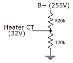
The first build of this design had AC heaters with the center tap referenced directly to ground. At normal listening levels, there was no hum audible (because I’m a wire-twisting champ). With the volume cranked past what I would listen to under normal circumstances, 60hz hum was there. Instead of immediately shitting a brick and rectifying the heater string to DC, I referenced the heaters to approximately 32V above ground with a simple voltage divider connected to B+.
Note that the Bill of Materials below does not include the resistors for the voltage divider or any parts for rectifying/regulating DC heaters. No two amps will be built exactly the same and so there is no standard solution. Start with plain-jane AC heaters; if there is too much hum, try referencing them positive; if there’s still too much hum, rectify and filter the crap out of them.
A reasonable output impedance
Phono preamps amplify the shit out of the cartridge’s signal. For example, let’s say the cart’s output is 5mV (a common value). That’s .005V or 200 times smaller than a 1V signal (typical output for many sources). But, we also have to factor in the 20db loss in the RIAA filter. So the required 200 times amplification is actually closer to 2,000 times. That’s a whole lot.
Most tubes with a high Mu also have a fairly high Rp. To get the amplification we want, we’re going to pay for it with a high output impedance. Now we could add a tube cathode follower, but that increases the power supply requirements and may prevent us from using those totally awesome VR tubes. It also makes things more expensive and means more heater wires and sources of noise. So instead we’re going to use solid state, namely the ZVN0545A MOSFET.
Before you start punching your computer monitor, please read this article on MOSFETs. You see? They aren’t so bad. Especially when we aren’t even using them for voltage amplification. In fact, solid state is darn good when we want current. The little ZVN0545A source follower will just sit at the output of the preamp and provide a respectable output impedance without shitting up the sound. This little MOSFET is like an awesome roadie. Doesn’t play the guitar, doesn’t hit on chicks, doesn’t throw up in your hair, he just hangs out quietly and makes sure everything gets to where it needs to be with maximum efficiency.
If you really can’t stand the sand, even after that kickass analogy, check out the Muchedumbre. That would also be a good way to lower your output impedance, but you’ll probably have to beef up your power supply.
Choosing a tube
If we want 2,000x voltage gain, we’re going to need a high Mu tube. If we want to use just two tubes per channel (RIAA sandwiched in between), the Mu has to be at least 45 (square root of 2,000). In actual circuits, the voltage amplification never reaches Mu, so we should shoot for a Mu a good deal higher than 45. While loading the tube with a CCS does allow us to get pretty close to Mu, I’d rather keep it simple and go with resistor loading here to preserve some of the characteristic tube sound. Pentodes can be noisy with small signals so we’re looking at triodes. That pretty much leaves us with 12AT7s and 12AX7s if we want to use something that’s easy to find. I don’t like the looks of the anode curves for 12AT7s, so 12AX7s it is. See? That was easy.
Math, math, beer
Ok, we’re using a 12AX7. Our slow decent into soul-crushing mathecaholism, begins with the output impedance of the tube. We know from the impedance page that the output impedance of a grounded cathode amplifier with a bypassed cathode (for maximum gain) is the plate resistance in parallel with the plate load:
Z = Rl || Rp
The plate resistance of a 12AX7 with ~250V on the anode is about 62,500 ohms. Let’s call the load 121,000 ohms for now. Because I said so. Survey says the output impedance should be around 41,000 ohms. Write that down. We will add this to the unknown series resistor (R1) and both will be in parallel with R0 (grid leak for the next stage). Solved for the series resistor:
R1 = (R1′ x R0) / (R0 – R1′) – Zout
The target total value of that arrangement (R1′) is determined by the first RIAA transition point equation and C1 (in uF):
R1′ * C1 = 2187
Now if we want to be able to easily find parts to build this design, C1 should be an easy to find value. Well let’s just use “1” then, right?
R1 = (2187 x R0) / (R0 – 2187) – 41,000
Now put in a 1M value for the grid leak R0 (common value) and…oh shit snacks. There’s no such thing as a negative resistor. The limiting factor here is the output impedance of the tube. A very low output impedance tube could hypothetically work with a C1 as large as 1uF, but we’ve got a high output impedance tube. So let’s try dividing by 100. If C1 is 0.01uF:
2187 / 0.01 = 218,700 = R1′
R1 = (218,700 x R0) / (R0 – 218,700) – 41,000
If we plug in the 1M grid leak resistor here, we get an R1 of 238k. That’s a lot more realistic and close enough to the standard 240k value. Yay! If not having the exact calculated value makes you itchy, remember that the Zout is an estimate anyways. Stop being a little bitch.
Here’s the easy part:
R1′ / R2 = 6.877
218,700 / 6.877 = R2 = 31.8k
There’s the R2. Again, use close-enough common values or resistors in series or parallel where you need to. For the final RIAA capacitor, C2, we have to take into account the input capacitance of the following stage (another 12AX7):
C1 / C2′ = 2.916
.01 / 2.916 = .0034 = C2′
C2′ – Cmiller = .0034 – .00015 = .0033 = C2
And what do you know, .0033uF is a common value. Hooray!
Bill of Materials
| Part | Quantity | Description |
| Iron | ||
| Allied 6K3VG | 1 | Power transformer |
| Triad C-3x | 1 | Choke |
| Sockets | ||
| Octal Sockets | 3 | Belton or similar |
| 9-pin sockets | 2 | Belton or similar, shielded if so desired |
| Active Devices | ||
| 5Y3GA Rectifier | 1 | |
| 12AX7 Dual-triode | 2 | |
| 0D3 VR Tube | 1 | |
| 0C3 VR Tube | 1 | |
| ZVN0545A MOSFET | 2 | |
| Jacks and Switches | ||
| DPDT Power Switch | 1 | |
| RCA Jacks | 4 | |
| IEC Power Inlet | 1 | |
| Fuse Holder and Fuse | 1 | |
| Capacitors | ||
| 2.0uf 600V+ | 2 | Output Coupling Cap |
| 0.047uf 600V+ | 2 | Interstage Coupling Cap |
| 0.01uf 600V+ | 2 | RIAA Cap |
| 0.0033uf 600V+ | 2 | RIAA Cap |
| 0.01uf 600V+ | 1 | VR Cap |
| 47uF 25V+ | 2 | Cathode Bypass Cap |
| 100uF 500V | 2 | Power filter capacitors |
| 15uf 500V | 1 | Power input capacitor |
| Resistors | ||
| 31,600 1/2W | 2 | Riaa Resistor |
| 121,000 1/2W | 6 | Load Resistor (Tube and MOSFET) |
| 1M 1/2W | 4 | Misc Resistor |
| 1,000 1/2W | 4 | Cathode Bias Resistor |
| 3,900 5W+ | 1 | VR Series Resistor |
| 47,000 1/2W | 2 | Cart Loading Resistor |
| 240,000 1/2W | 2 | Series Resistor |
| 510 1/2W | 2 | Mosfet Gate Stopper |
| 100 1/2W | 4 | Tube Gate Stoppers |
| 1,200 3W+ | 1 | CRC Resistor |
| Misc | ||
| 12V Zener | 2 | Mosfet Protection |
| Chassis | 1 | Give yourself lots of room |
Note: the above BoM does not include extra parts that you may need to eliminate heater-induced hum (see section on noise above), this project works with tiny signals and assumes you have some working knowledge of troubleshooting noise and hum
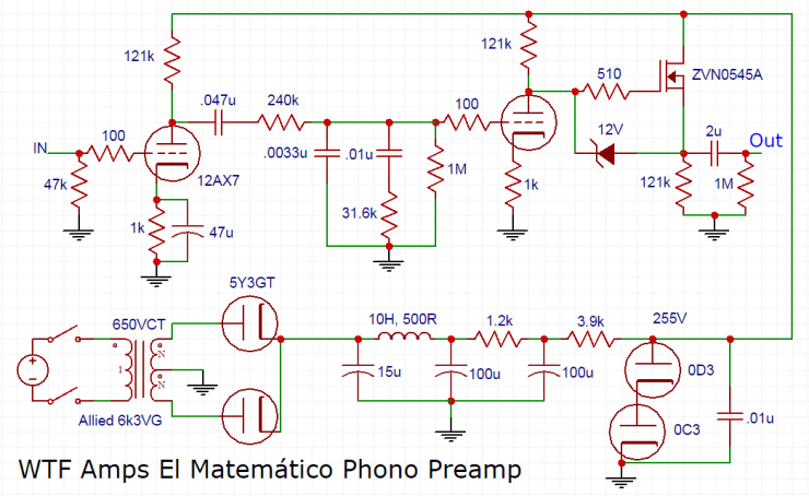
Schematic
TL;DR Features
- Heavily filtered and regulated power supply eliminates B+ ripple and improves consistency of operation to overcome voltage fluctuations and change in tube performance over time
- VR tubes look cool AF
- Low value RIAA capacitors allow for larger value resistors in RIAA network, further lessening the impact of tube changes with age (at the theoretical cost of Johnson–Nyquist noise)
- MOSFET source follower output provides a low output impedance for better matching with other components
- Common 12AX7 gain stage tubes are in current production and readily available
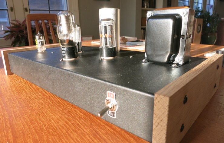
Build Pics
Click here for build pictures and wiring tips
Another build example from a diyaudio.com user:
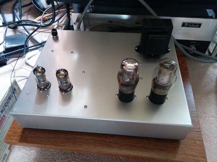
Have fun. Be safe. Enjoy music.
