

Tubes make great high voltage devices all by themselves, but they can’t usually handle much current when it comes to playing jams on your speakers. Speakers act a lot like resistors as far as your amplifier is concerned, and the power (wattage) you send to them is a product of voltage and current. To review a couple basic power calculations, we have:
Watts = Volts * Amps (what your amp produces)
Watts = Amps ^2 * Ohms (the limiting power equivalent at the speaker)
Your tube can produce all the voltage it wants, but if it doesn’t have enough current, it’s not going to produce enough power at the speaker. So how do we take high voltage and low current and make low voltage and high current? Hunks of iron, copper, and electromagnetic badassery (AKA output transformers).
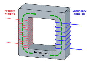
Primary and Secondary
The primary and secondary are the input and output of the transformer, respectively. In transformer coupled tube amps, high voltage goes through the primary and high current comes out of the secondary. The primary side of the output transformer often serves as the plate load for the output tube in the same way a resistor might serve as a plate load in a grounded cathode amplifier:

Varying current through the tube (controlled by the grid) produces varying voltage across the output transformer primary. The value of the primary load is referred to as its impedance. Impedance is kind of like the AC version of DC resistance. Don’t worry if that doesn’t mean anything to you yet; impedance is complicated shit. Generally, we want a fairly high primary impedance (2,500 to 10,000 ohms) for the tube in order to produce a good balance of power and low distortion.
On the ass end of the output transformer, we have the secondary. The secondary is what you connect to your speakers. The rated impedance of the secondary should match your speaker (usually 4 or 8 ohms), so speaker impedance is an important factor to consider when choosing an output transformer. Some output transformers have multiple secondary ‘taps’ that allow you to use speakers of different impedance without having to recalculate or optimize your amp design.
Assuming your amplifier is already designed and built for 4 ohm speakers, you can usually use an 8 ohm speaker on the 4 ohm secondary tap. This will lead to lower power, but also lower distortion. You probably won’t blow shit up (at least not immediately) if you connect a 4 ohm speaker to an 8 ohm tap on an amplifier, but it is going to increase distortion and may cause your tube to operate past its maximum dissipation spec (shortening its lifespan). As we’re about to cover though, impedance is a little bit of a mindf*%k.
Turns Ratio and Impedance
Output transformers are built by wizards and sometimes shamans. They take a couple of pieces of insulated wire and wind them around a chunk of conductive moon metal. When the wizard (or shaman) applies a voltage to one wire, it creates a magnetic field in the moon metal and this magnetic field induces a voltage in the other wire. If the input wire (primary) has ten times the number of turns as the output wire (secondary), the voltage in the output wire will be one tenth of the voltage applied to the input wire. That’s what is referred to by us muggles as a turns ratio.
The turns ratio and the load connected to the secondary determines the impedance that your tube sees at the primary. In fact, the primary impedance of an output transformer will always be the square of the turns ratio times the load on the secondary. If you’re still conscious, let’s break it down with a hypothetical:
Say you have a transformer with twice as many turns on the primary as on the secondary. This means you have a turns ratio of 2 (to 1).
Let’s connect a 10 ohm resistor to the secondary and apply 20V to the primary.
Because you have half as many turns on the secondary, the 20V on the primary becomes 10V on the secondary.
The 10 volts on the secondary divided by 10 ohms gives you 1 amp of current (V / R = I). Ten volts times 1 amp is also 10 watts of power (V * I = W).
That 10 watts must also be occurring at the primary side (assuming the transformer is perfectly efficient). Ten watts divided by the 20 volts on the primary gives you one half of an amp (W / V = I).
Twenty volts on the primary divided by one half an amp gives you 40 ohms (V / I = R).
Forty ohms on the primary divided by 10 ohms on the secondary gives you 4. Four is the the turns ratio (2) squared.
The forty ohms in this example is the impedance that a tube would see at the primary with a 2:1 turns ratio output transformer and 10 ohms on the secondary. If we put 5 ohms on the secondary, the tube would only see 20 ohms (5 * 2^2). If we put 100 ohms on the secondary, the tube would see 400 ohms (100 * 2^2). This is all to say that primary impedance is not inherent to an output transformer; it depends on the load. When you are drawing loadlines for power stages, you should keep in mind what your transformer will be connected to.
Additional Mindf#%kery
Impedance of an output transformer, due to the nature of inductors, is frequency dependent. Let that shit sink in for a hot minute. In other words, the primary impedance your output tube sees at 20hz is not necessarily the same as the impedance at 10,000hz. If you want to keep the impedance high across all frequencies (ensuring good signal transfer), you also have to factor in the inductance of the output transformer primary (a spec usually provided by the manufacturer) and the frequency of interest. You can find the -3db cutoff frequency (f) relative to the nominal impedance (Z) of your output transformer primary (AKA reflected impedance in parallel with the tube’s plate resistance) by using the transformer’s primary inductance (L):
f = Z / (2 * pi * L)
Similarly, you can decide how much primary inductance you need for a given -3db frequency with:
L = Z / (2 * pi * f)
The most we mere mortals can do when designing an amplifier is to optimize a loadline based on the output transformer’s specs and hope to shit that it will stay a good loadline at all the other relevant audio frequencies. All this math is one of the reasons that tube heads will straight up murder each other over a good set of output iron.
To complicated matters further (because, why not?), your speakers do not present a constant impedance to the secondary, meaning the speakers themselves are also turning your beautiful calculations into pretzels with their kinky ass impedance dips and spikes.
Didn’t all this seem easier when it was just magic and moon metal?
Single-Ended vs Push-Pull
Single-ended amplifiers draw (sometimes significant) current through the output transformer. Push-pull transformers connect two tubes in an arrangement that creates two equal and opposite currents, which cancel each other out (in a perfect amplifier). Because of this difference, single-ended output transformers need to have an air gap to prevent current saturation (a bad thing), but push-pull output transformers do not. This tends to make single-ended transformers much larger and more expensive for the same amount of power.
You cannot generally use a push-pull transformer for a single-ended amplifier without some creative MacGyvering (like a parafeed amplifier). Single-ended transformers do not usually allow you to connect two tubes in the proper way for push-pull operation. In summary, a pair of output transformers will usually only work for one topology or the other, but not both.
