

As with most audio designs, you should start from the load you’re driving and back through the amp’s stages to the input that the amp will be fed. Although this amp started with the power supply, we have a wide range of voltages it can produce and more than enough current for a small SET. The rest of the build progressed in the usual way: from the outputs to the input.
Load requirements
I like headphones. I like speakers, too. Unfortunately, amps that handle both well are not so common. I’m not sure why that should be the case. A low power speaker + headphone amp makes a great desktop companion and really isn’t so difficult to accomplish with tubes. To demonstrate this, we have to talk a little bit about the logarithmic relationship between amplifier power and perceived sound levels.
10 * log (power) = decibel
10db increase (10x the power) is generally perceived as twice as loud
Speakers
Most desktop-size speakers are in the mid 80s db/W @ 1m sensitivity wise. We’ll call it 85db for the sake of calculating stuff. The sensitivity rating means that with one watt of power, you’ll get 85db of sound at one meter away. For reference, 80db is pretty loud. It’s about the level of a running garbage disposal or an alarm clock. You can listen at 85db for eight hours before you start risking hearing loss; this is also the sound level at which OSHA will f%*k your sh!t up.
For nearfield listening, there may be less than a meter between you and the speakers. When you halve the listening distance, you can add 6db to the sensitivity rating. Now with the same 85db speakers you’re getting 91db at half a meter with one watt of power. You should probably turn it down a touch to protect your hearing (2 hours at 91db is the maximum recommended duration):
10 * log (0.5 W) = – 3 db
Every halving of the power deducts only 3db, so one quarter of the power (0.25W) gets you back down 6db to a non-litigious 85db. If you want to listen at 80db (which is comfortably loud, believe me) you only need around 100mW. Aren’t decibels fun?
This all goes to say that you do not need a whole bunch of power for nearfield listening, even if the speakers have a low sensitivity rating. And if you have high sensitivity speakers in your main system, a single-ended low wattage amplifier can work there, too. If you have speakers rated at 95 db/W @ 1m and like to listen around 80db, listening at two meters requires only 125mW of power.
The above discussion of power and decibels does not take into account dynamic headroom. It’s always good to have some power in reserve for music dynamics. Or for cranking it when OSHA isn’t paying attention. I try to have at least 10db-20db to spare (10-100x the power) over what I expect my average listening levels to be. If you didn’t fall asleep while I fapped around with decibels and logarithmic math, you noticed that average, safe listening levels (80-85db) need only a fraction of a watt with average sensitivity speakers nearfield or high sensitivity speakers at a regular distance. Just a couple watts (10x the power) will often get you comfortable listening levels and leave enough headroom to prevent too much dynamic compression. Just make them high quality watts.
Headphones
In contrast to speakers, headphones work in milliwatt ratings. Most are mid 90s db/mW. We’ll call it 95db for the sake of calculating stuff. This rating means that with 1 mW of power (1/1000th of a watt), you’ll get 95db of sound. You can safely listen at this level for about an hour. No, headphones don’t need a lot of power at all. Yes, just a couple of watts are plenty capable of harming your hearing.
The other quirk about designing for headphones is the huge array of impedance ratings they come in. Today, 32Ω seems to have become the average, but there are still high quality designs around 300Ω as well. Addressing the large difference in impedance loads, while maintaining a respectable output power, is less straightforward than it may seem.
Let’s say we want to provide at least 100mW (which is 20db of headroom over nominal 1mW rating) into any headphone load we are likely to encounter. We know that power is inversely proportional to the load and has an exponential relationship to voltage. Let’s solve for voltage given our requirements for headphones of varying impedance:
Power = Voltage² / Impedance
Voltage = √(Power * Impedance)
√(32 Ω * 0.1 W) = 1.8 V
√(150 Ω * 0.1 W) = 3.9 V
√(300 Ω * 0.1 W) = 5.5 V
So, if we want to put at least 100mW into 300Ω, we’ll need 5.5V from the amp. Assuming we are going to use only one output transformer tap for everything (speakers, headphones, etc), how much power is the same 5.5V into an 8Ω speaker?
5.5² V / 8 Ω = 3.8 W
If we design an amp that can put 4 watts into 8Ω, the maximum output voltage will be 5.5 V and so we’ll get 100 mW into 300Ω. Now assuming the 5.5V is fixed (it isn’t really, but more on that in a bit), how much power does this put into the other headphone loads?
5.5² V / 8 Ω = 3.8 W
5.5² V / 32 Ω = 1 W
5.5² V / 150 Ω = 200 mW
5.5² V / 300 Ω = 100 mW
Ok, we clearly have more power than needed for low impedance headphones. But we have it for the right reason; it simplifies the design.
Output Stage
Getting about 4W output for speakers gives us plenty of options when it comes to tubes. If we narrow down options to current-production types, triode-strapped beam tetrodes are very appealing (read: cheap and easy to find). Triode-strapping a pentode gives us the desireable triode traits (lower distortion and lower output impedance) without the typically high cost of power triodes (2A3, 300B, etc). Popular types in order of descending heater current requirement are the KT88, EL34, and 6L6GC. All of these tubes work well with a 5K:8 Ω output transformer and this just so happens to be a common winding ratio.
Taking into account heater current requirements, space constraints, output target, and (most importantly) what I had in my tube stash, I decided to go with the venerable 6L6GC output tube. This circuit could easily be adapted to the EL34 or KT88 if you so desire.
If the output transformer presents the tube with a 5kΩ impedance and we want 4W of power, how much voltage will the tube need to swing?
Power = V² / Z
√(4W * 5kΩ) = 140 Vrms
We need 140Vrms on the primary. This is divided down by the turns ratio of the transformer, which is:
√(Pri Ω / Sec Ω) = Turns Ratio
√(5000 / 8) = 25
The 140Vrms on the primary divided by the turns ratio of 25 gives us 5.6Vrms on the secondary. This matches the earlier calculations, so we haven’t farted anything up. Now, 140Vrms is 400V peak to peak (140Vrms * 2√2) and this is how much the tube’s anode must swing about the quiescent point. Given a 5,000Ω load and the need to swing +/- 200V, we can finally look at some load lines!
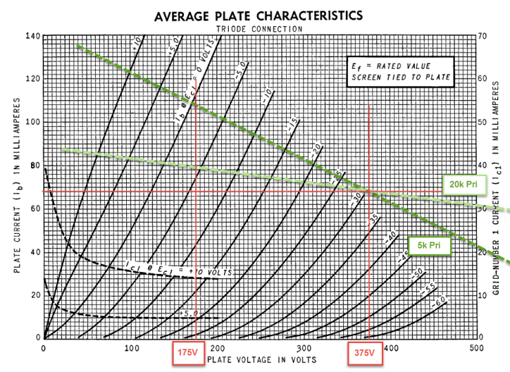
With a quiescent point around 375V and 65mA, the 5k loadline has room for 200V of negative swing (down to 175V). Although the graph does not extend far enough to see, the anode should be able to swing up to 575V as well (though the shape of the curves gets less promising at high voltage, indicating some even harmonic distortion). The 20k load line (which is a 32Ω load on the secondary of a transformer with a turns ratio of 25) is flatter and so it has more space to swing negative before hitting the 0V grid line, indicating that actual full power output into 32Ω is higher than the 1W we calculated earlier. Because the load line is also flatter, the higher value load will most likely result in less distortion.
Our quiescent point of 375V and 65mA corresponds to a grid voltage of about -30V. We’ll therefore get full power when the grid swings between 0V and -60V. That 60 Vp-p will come from our input tube.
Input tube and loading
Let’s say we have a 2Vrms input signal. This is equivalent to 2V * 2√2 or 5.65 Vp-p. If we need to swing 60 Vp-p (see output stage above) with an input of 5.65 Vp-p, we want a gain of at least 60 / 5.65 = 11. Usually we want the output stage to clip before the input stage, so the Mu of the input tube (and gain of the stage) should be higher than 11. A little extra gain is also nice in case we have low output sources. Let’s call it a goal of at least 15x gain.
I have heard nothing but good things about the 12BH7A dual triode but had not used it in a design until this amp. The 12BH7A has good specs on paper: Mu 17, Rp 5,500Ω, plate dissipation 3.5W, plate voltage 450V. To top it off, it has curves in all the right places, like the Christina Rene Hendricks of 9 pin tubes. The Mu of 17 is marginal though, so we’re going to do what we can to maximize this. That means paying close attention to how we load the triodes.
Resistor
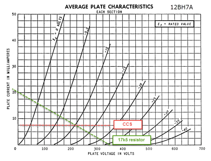
A resistor is the standard way of loading input stage tubes. There ain’t nothing wrong with that. If we had a higher gain input tube (6DJ8, for example), that’s probably also the way I would go. With the 12BH7A, however, a resistor load of 17k5 (approximately 3x the Rp) results in a voltage gain of only about 13x:
Gain (w/ bypassed cathode resistor) = Mu * Rl / (Rp + Rl)
17 * 5k5 / (5k5 + 17k5) = 13
This gain calculation is supported by inspecting the plate curves (below). Between the -10V and -15V grid lines, the plate swings between about 210V and 270V (60V plate swing divided by 5V grid swing is 12x voltage gain). That might work with a full 2Vrms input, but it falls short of the 15x goal so that we can be sure we are clipping the output before we are clipping the input.
CCS
A CCS, like the 10M45S used in the Papa Rusa, presents an ‘infinite’ load to the anode. On paper, this lets us preserve the entire Mu of 17 for the stage’s voltage gain. In practice, this infinite load is in parallel with the grid leak resistor of the output stage, so our load is very, very large, but not quite infinite. The anode voltage with a CCS is limited by the B+ with this kind of configuration, but that is not a problem here at all.
We can build a CCS out of solid state or vacuum tubes, though depletion mode n-channel MOSFETs (like the 10M45S or DN2540) seem to have cornered the market. They are simple to use, carry decent voltage ratings, and take up very little space. I use them in lots of builds.
But what if we don’t have room or heater current for a tube CCS and don’t want to use any solid state in the amp? After all, the regulated power supply feeding this amp is already a glass-lover’s wet dream with nary a chip in sight. Maybe we fear an EMP apocalypse or maybe we want to avoid any component that might go poof with a slip of a meter probe. Maybe we just want to do this old school, iron laden, no apologies classic vacuum tube through and through.
Choke
There is another passive component that is less commonly seen as small signal plate loads: the inductor. An inductor (AKA “choke” in tube parlance) presents a high impedance; that is to say that it passes DC just fine, but opposes AC signals. This impedance rises with frequency according to:
Z = 2 * Pi * f * L
Where “L” is the value of the choke in henries and “f” is the frequency in question. Inductive impedance is also at work in the primary of output transformers, so any potential sonic impact of an inductive load in the input stage is not going to be out of keeping with our puritanical old school vacuum tube theme.
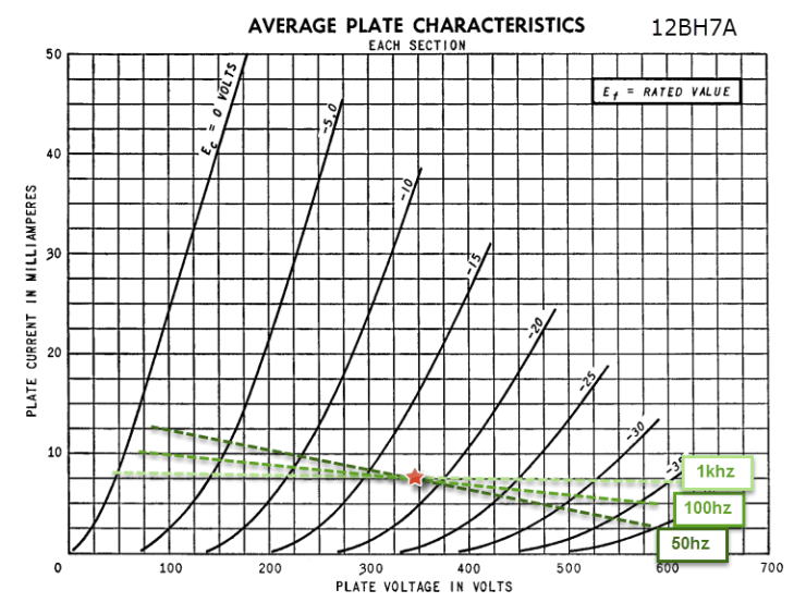
The biggest problem with chokes is that they’re damn expensive. In many cases they are pricier than modest output transformers. If you’ve understood anything from this website it’s that I’m a cheapskate with a tube addiction. Luckily, Hammond has our back once again. The Hammond 156C is a 150H choke specified for 8mA of DC current with a rated DCR of 3k7 (3k25 actually measured with my pair). This 150H provides a huge impedance (practically infinite, like a CCS) once you get up to a few hundred hertz, maximizing the gain we can wring out of our input tube.
Using a choke as the load on our 12BH7A puts its anode at the B+ voltage minus the voltage dropped due to the DCR. If we bias the tube for 8mA, we’ll drop 3k25 * .008A = 26V and our 12BH7A will operate at about 325-350V on the anode. We like to run them hot, but the little Christina Rene Hendricks can take it (seriously, Google her). We end up with a load that increases with frequency, but is still at least 3x the Rp at 20hz. Our load line(s) look about like:
Spreadsheet for calculations
All this frequency dependent bugaboo makes for lots of numbers to try and keep track of. I created a spreadsheet that will calculate the resulting frequency response of a two-stage SET with a choke loaded input. It factors in the effects of the choke’s value, the grid leak resistor for the output stage, the Miller Effect of the output tube, the coupling cap, and the inductance of the output transformer primary. It looks like we lose a decibel or two at the frequency extremes on the input due to inductance or Miller Effect. Can you hear that missing decibel at the frequency extreme with musical content? I don’t know for sure, but I doubt it. Does this amp sound good? You bet your big busted redhead it does.

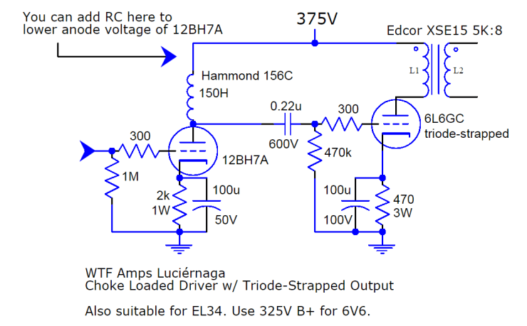
Schematic & Construction
This schematic uses a slightly cooler operating point than the 6L6GC loadline above so that I could be sure I was dropping plenty of volts in the power supply and letting the 6AS7 pass tube do it’s thing. A B+ around 400V gets back to the previously illustrated loadline without any changes to component vales shown below.
Click picture for some additional build photos.

Bill of Materials
| Luciérnaga Amplifier | ||
| Resistors | ||
| 2 | 1M, 1/4W+ | grid reference for 12AX7 |
| 4 | 300, 1/4W+ | grid stopper resistors |
| 2 | 2k, 1W+ | cathode bias for 12BH7A |
| 2 | 470k, 1/4W+ | grid reference for 6L6GC |
| 2 | 470, 3W+ | cathode bias for 6L6GC |
| 1 | 100k, audio taper pot | for volume control |
| Capacitors | ||
| 2 | 100u, 50V+ | cathode bypass for 12BH7A |
| 2 | 100u, 100V+ | cathode bypass for 6L6GC |
| 2 | .22u, 600V+ | coupling capacitors |
| Tubes | ||
| 1 | 12BH7A | voltage gain stage, dual triode |
| 2 | 6L6GC | output stage, triode strapped |
| Iron | ||
| 2 | Hammond 156C | anode load chokes, 150H+ |
| 2 | Edcor XSE15 5k:8 | or similar 5k primary output transformer |
| Hardware | ||
| 1 | 9 pin socket | for 12BH7A |
| 2 | octal socket | for 6L6GC |
| 2 | RCA jacks | for input |
| 2 | binding post sets | for speakers |
| 1 | headphone jack | for headphones |
| 1 | DPDT switch | for headphone/speaker selection |
Potential tweaks
CCS instead of a choke
So, you don’t like that calculated decibel dip in the input stage bass response and you don’t mind a bit of sand? Good on you. Replace the chokes with a CCS MOSFET and a small heatsink (~2W dissipation) and you’ll probably fix it (in measurements at least). Note this will require a different cathode resistor on the 12BH7A, but it’s otherwise a simple swap.
The audible bass performance of the choke loaded amp is every bit as good as one of my other daily driver amps with a CCS loaded input and similar output transformers, though it is difficult to say how much of this is due to the over-designed power supply and how much is the input tube loading.
Drop the plate voltage of the input tube
If you can’t find a 12BH7A, there are lots of tubes that would work on the input of this amp. The 12AU7 or 6CG7 are good candidates, but their plate voltage max is typically rated for 300V. Insert a simple RC between the choke and 6L6GC to drop some voltage (10k 2W resistor should do the trick). Note this will require adjusting the cathode resistor to get around 5-10mA.
Output tubes
There are also plenty of output tube options. I wired my amp to be able to swap 6L6GCs or 6V6s with just a twist of the power supply voltage knob. If you wire the sockets correctly and have the heater current capacity, EL34s or KT88s will also be an easy drop in swap (note g3 is not internally tied to the cathode on EL34s).
Final Verdict
I’ve built a good number of amps over the course of my hobby. Some of them just make things louder, which is exactly what amps are supposed to do. I don’t know whether it’s the choke loads, the input tube, or the extra time spent on the power supply of this amp, but the Luciérnaga (Spanish for firefly) gave me goosebumps from the first listen.
Headphone listening has an extra intimate quality that I don’t often hear. Most surprising is how ‘strong’ this amp sounds on speakers. You wouldn’t believe it is only 4W from the way it controls the rhythm section with musical content. If I’m aloud to speculate, this probably has a lot to do with the super low noise floor and low power supply output impedance.
If you have room on your desk for such a monstrosity, I highly recommend giving this design a shot.
Have fun. Be Safe. Enjoy Music.
