

In contrast to the confusing AF series pass regulator, a shunt regulator can be made with as little as a single tube and its operation should be fairly familiar to you after reading about grounded cathode amplifiers. Note that just because it can be DIY’d with a single tube doesn’t mean it should only be done with a single tube (you cheapskate).
AC Shunt Regulators
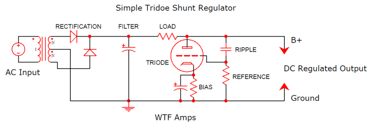
In its simplest form, the DC output of your rectifier and filter is fed into a resistor load. The other end of the resistor is connected to the anode of a triode. The output is taken from this junction. We know that the bias of a tube (voltage difference between grid and cathode) in a grounded cathode arrangement determines the anode voltage. In a shunt regulator we set the output voltage using this same principal.
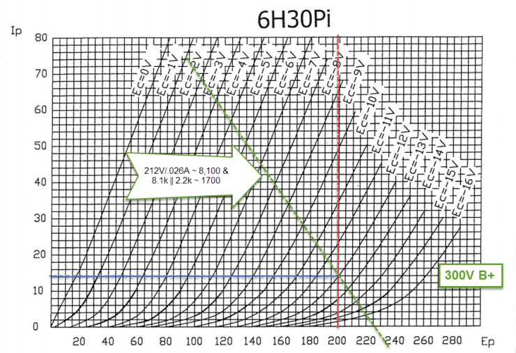
Assume for a moment that we have a 300V supply and we want to drop it to 200V with a 6H30pi shunt follower. We therefore want to choose an operating point along the red line (200V). To do so we also need to decide how much current we want through the tube. Let’s put 14mA (blue line) through the tube because it hits a grid line and I’m too lazy to start using fractions.

So if we want 14mA through the tube and 200V at the anode (which is also the output of the shunt regulator), we need the grid to be 12V more negative than the cathode. If we use a cathode resistor, the actual voltage between anode and ground will then be 200V + 12V. Damnit. Ok, let’s pretend we want 212V regulated output instead. With 14mA and a 12V drop we need a 12/.014 = 850 ohm cathode resistor. Don’t bother looking for one; they don’t exist because reality sucks. Good thing this is pretend. Like in a grounded cathode amplifier, the grid is referenced to ground with a grid leak resistor (‘reference’ in the diagram) so that the cathode is raised above the grid.
So the tube is going to try to set 200V at its anode plus 12V across the cathode resistor. What happens to the other 88V (300V B+ less 212V for the tube)? That will be dropped across the load resistor. To figure out that value, we need to decide how much current the load connected to the output of the shunt regulator will draw (because all the current flows through the load resistor). Let’s say the load will be 26mA so that we have 40mA total through the load resistor. You know about Ohm’s Law so you can easily figure out the load resistor’s required value. Hint: it rhymes with 2,200.
Note: If we want to fine tune the output to the original 200V at this point, we can alter the current through the tube by adjusting its bias or we can change the size of the series resistor.
Finally, we want the grid to know about ripple on the output so that it can counteract it at the anode. To do that, we connect it to the output with a capacitor (this is also a form of feedback). The capacitor doesn’t change the DC bias of the tube, but it does let AC signals (like ripple) through. Grounded cathodes are inverting amplifiers and so if the power supply ripples, the grid tells the anode to do the opposite.
Transconducance is the engine that powers this action because transconductance is the ability of the tube to turn a voltage signal into a current (and the current through the tube helps control the voltage drop across the load resistor).
The last thing we should consider is how the output and load resistor combine to load the tube. This is where the importance of your bias point and the current demands of what you connect to the shunt regulator come into play. The load is at 212V and draws 26mA so it is the equivalent of about a 8,100 ohm load. From the tube’s perspective this is parallel to the 2,200 load resistor.
If the current demands of your load are too high, the loadline will get too steep. Same thing if the load resistor is too small.
DC Shunt Regulators
We can also use shunt supplies with a fixed DC reference (zener, LED, etc) in the cathode and a voltage divider on the grid to create a shunt supply that does not vary with mains voltage and still scrubs away ripple. The principles and biasing are basically the same as the above but the AC-only version is a little easier to understand at first glance.
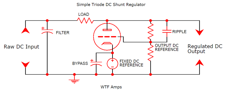
Because the cathode’s voltage reference is fixed, feedback from the grid will always try to pull the output to the same DC voltage potential. This is generally harder on the tube because the only way for it to affect a lower voltage (if it is too high from the raw DC input) is to conduct harder, thus increasing dissipation and generally getting all hot and bothered.
Designed correctly, if the power supply voltage goes up, the tube conducts harder and drops more volts across the load resistor (because the cathode voltage reference doesn’t change). If the power supply’s voltage goes down, the tube conducts less to drop fewer volts across the resistor. Meanwhile, the grid is fighting the ripple tooth and nail like one of those alley cats that looks really friendly until you f#&k with it and it somehow gets your SSN and totally ruins your credit score. F*%king cats.
