Fender AA864 Blackface on the bench

IMG_20180827_194055151

Came with an assortment of tubes. The power tubes are mismatched brand (I imagine not matched for bias, Gm, etc). The “ECC083” does not have a brand marking but the internals look like nice quality construction. All tubes are visually fine.

IMG_20180827_194201666

The fuse in the amp is a 3A fast blow type. Back panel calls for 2A.

IMG_20180827_200134435

Bolt heads show it’s been opened up before. We’ll see why later.

IMG_20180827_200041410

Very clean chassis. Sockets are in decent shape.

IMG_20180827_195837575IMG_20180827_195841427IMG_20180827_195844585

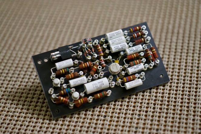
Gotta love vintage point to point and turret/eyelet construction. Again, nice and clean here. Fiberboards are in good shape, minor warping from age/storage. Cloth covered wire. Rectifier diodes and bias network in the top of the pic will be replaced.

IMG_20180827_200343068

Power filter caps. The larger orange cap on the right appears to be the reason it was opened up in the past (probably a long time ago). Non-original, non-spec, not that it matters. These will all be replaced.

IMG_20180827_201150546_LL

Old tag. Not sure about production number. Maybe May of 1967?

What’s on the bench

I realized I have mentioned a bigger project in the works for a while now but I haven’t provided any real details. Here’s the basic schematic. This is a two stage push pull amp using a long tail pair shunt cascode phase splitter up front (that’s a mouth full). The schematic does not have all the details yet as it is untested, but you get the general idea of what I’m going for.

I made two PCBs for this project due to all the little TO92 and other SS parts. The first PCB is a fairly simple MOSFET series regulator using a LR8 as the voltage reference. This will feed the input stage of the monoblock. The input stage will consist of a pair of shunt regulator PCBs with (probably) a simple 10M45 tail CCS. Bartola Valves has some great articles on the shunt cascode design, in turn based on experiments by Rod Coleman.

I’m shooting for about 20W in triode mode without feedback. I’ll likely also experiment with UL and NFB at higher output levels, too. The output transformers are Hammond 1650N. If the project turns out well, the next layer of complexity will be a direct coupled MOSFET driver for AB2 operation. For the first build, I’ll keep it nice and easy cathode bias though.


Schitt is getting into DIY, except they’re definitely not

Pic from Schitt product page

If you’ve missed the recent hubbub, Schitt is launching a line of drink coasters. It just so happens that these coasters double as unsupported DIY projects with scarce documentation.

The schematic shows a 6418 sub-miniature triode direct connected to an AB push-pull transistor output stage (cap coupled). Power is a blistering 30V to the tube and 15V to the output stage, cleverly derived with a bridge doubler and regulated with LM317s.

Schitt is hedging the product with extra coy advertising (AKA the Schitt Shtick) and reinforcing in several places that they are not a DIY company. Hence the product is a coaster, not a miniature hybrid amplifier. It will come at no surprise to Schitt when DIY documentation is created by early adopter hobbyist communities, I’m sure.

Some of the quoted specs:

  • Frequency Response: not terrible, but not exciting (like 10-100K, -1dB or so)
  • Power Output: much less than anything else we make (like, less than Fulla 2, maybe 400mW into 32 ohms, all in, 10% THD or so)
  • THD: about 0.5% at 1V RMS (6418 tubes) or about 1.5% at 1V RMS (6088 tubes)
  • IMD: didn’t bother measuring, this amp ain’t about measurement
  • Output Impedance: about 8 ohms (yes, 8, not 0.8, not 0.08), in case you didn’t get the memo, this ain’t a high-performance amp

What is it about Schitt’s non-committal and self-effacing copy that gets so many people so excited?  Why did I just buy a small lot of 6418s? Why are coasters already on the way to me?

Schitt, you sly dogs.

Letters to WTF: is tube linearity just a matter of lower gain and higher operating voltage? Or it is inherited with the medium – vacuum vs semiconductor?

Generalizations are difficult to make, but you can look at the theoretical mechanisms of operation for some interesting nuggets.


In a tube, current is transferred between anode and cathode by the space charge in a vacuum. Child’s Law states that current in a vacuum is directly proportional to anode voltage (to three halves power) and inversely proportional to the distance between electrodes (squared). The speed of electrons depends solely on the applied voltage.


In semiconductors constructed of doped sandwiches of semiconductor material, Child’s Law doesn’t apply. Here we use the Mott-Gurney law. This states that the current density in a semiconductor is directly proportional to anode voltage (squared) and inversely proportional to the thickness of said material (cubed). The speed of the electrons depends on both the electron mobility of the semiconductor (assumed to be constant) and the applied voltage.

There are extra constants for calculations in either case, but notice the similarities. In both cases, we can assume distance between electrodes (whether separated by a semiconductor or a vacuum) doesn’t change. The difference here is the power for the voltage term. The generalization is that current density through a vacuum is less affected by changes in anode voltage than is current through a semiconductor.

Is this the theoretical mechanism to explain the heuristic that vacuum tubes are more linear than transistors? Maybe…at the very least it’s an interesting observation. In reality, geometry, application, and other factors matter, aside from just materials. Some tubes are more linear than others just as some transistors are more linear than others. There are bad ways to bias and operate tubes just as there are good ways to bias and operate transistors.

One little project comes to fruition

Early this year, I wrote a post about simple RIAA correction with opamps. Although it doesn’t involve tubes (yet), I recently completed a PCB-based build based on this post. This was both to test the calculations/theory as well as good practice in PCB design.

This ultra-simple phono preamp runs on just a pair of 9V batteries for power and utilizes a mix of feedback and passive EQ for RIAA correction. The batteries should last about 24 hours (playing time), but a bipolar AC-derived supply could be substituted without trouble. Gain is easy to adjust with just a couple of resistors (set at 40db in my build). The bill of materials runs about $25 with 5532 opamps and 5% tolerance WIMAs.

I’m planning on building a couple of these with coworkers and basing build instructions and any revisions on the experience. I do have some extra boards from this first run. Shoot me an email if interested!

New Page: Phase Splitters

It’s no secret that I’ve been working on a larger push pull project, but it may still be a surprise because progress has been so slow. Don’t get me wrong though, dad stuff is the best.

IMG_20180619_125805547.jpg

Writing time is sometimes easier to come across than bench time, so there’s a new overview of phase splitters page for your enjoyment. Happy holiday!

Edcor has new secondary options

Finding output transformers with turns ratios suitable for headphones used to be an exercise in futility (and endless eBay refreshing). As the market for high-end headphone amplification has grown over the past few years, it seems like Edcor has taken notice. I’m really happy to see some new options for high impedance headphone transformers on the Edcor website. Relative to vintage UTC or custom winding, these look like very affordable options:

edcor heapdhone OPT options.png

In the past I’ve resorted to matching transformers in a parafeed arrangement or speaker transformers with low impedance headphones. I look forward to trying some of these transformers in future builds!