Direct coupled SET proposal

I’ve had a few 6CB5As kicking around for a while waiting for a project. The 6CB5A has been documented by Thomas Mayer and Ale Moglia, among others, as a great option for triode strapping. Thing is, I like trying new things when I build and repeating a cap coupled formula for a two stage single-ended amp just wasn’t making it to my short list of projects (which I don’t quite have time for anyways).

A recent discussion reminded me of an idea to use the shunt cascode topology to direct couple to a single-ended output. It required some extra power supply rails, including a fairly large negative rail. These requirements aren’t anything too unusual; you see them with Morgan Jone’s Crystal Palace amplifier or any kind of fixed bias scheme (in a way).

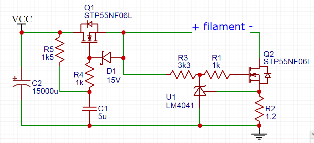
Anyways, the more recent discussion reminded me of a thread discussing a novel way of direct coupling two stages by stacking the power supplies. This is kind of similar to the Free Lunch AKA Monkey on a Stick arrangement. Applying this idea to my original shunt cascode brainstorm lead me to this:

We have a shunt cascode input stage. The output resistor (R2) idles at about 75V across it. This feeds a MOSFET source follower, which will have just a couple volts less on its output. So we have a very low impedance output at around 75V above ground and we want to direct couple that to the next stage. This is where I think it gets exciting.

We raise the cathode of the output stage so that it is positive relative to the grid (at 75V) by floating the output tube power supply (V2). The voltage we float it at is roughly equal to the target bias voltage plus half the target output swing. In other words, we raise it by twice the bias voltage for A1 or twice plus a bit for A2.

The output tube anode is connected normally and the cathode returns to the point where the output supply (V2) floats on the bias supply (V1). Our input stage is powered by another supply floating on the bias supply (V3). Our input and grid driving circuits are all referenced to ground and direct coupled. We can set the output bias by adjusting the current through R2.

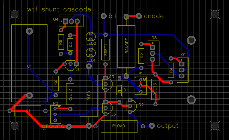
Here’s a more fleshed out version:

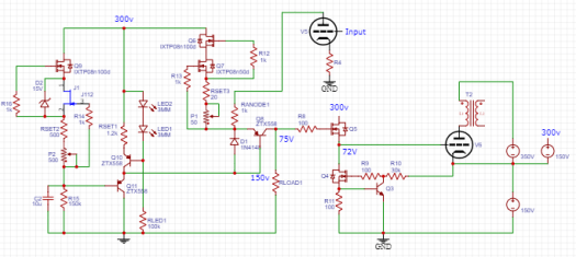
It looks like a lot in the schematic, but I’ve already got shunt cascode and grid driver circuits on small PCBs. The power supplies don’t need to be anything exotic in this case as the input has decent PSRR already. The higher current output could use simple CLC filters as well.

Will I build it? I hope eventually. By summer I hope to have the workshop basically finished. I’m already enjoying having all the tools and parts in one (heated) space!

New page: gyrators

Ok, so what we often call a gyrator is not technically a gyrator. This page is named after the circuit popularly referred to as a gyrator, not an actual gyrator.

I’m developing a little PCB for a simple gyrator circuit to be used in an upcoming integrated preamp project (2nd stage of phono circuit: needs gain and low enough output impedance to drive a volume pot). The thing that’s most intriguing to me at this point is how a gyrator lets you set an anode voltage rather than anode current (but still maintains a high impedance for AC). On paper, this looks more flexible in rolling compatible pinout tubes than setting a current. And what the heck, it’s a new circuit to try!

See the new page here!

Simple discrete CCS

You’ve already read the CCS and loadlines page that discusses how a constant current source affects a tube’s behavior. You have also seen CCS’s made from depletion mode MOSFETs and LM317’s in projects like the Papa Rusa and El Estudiante (respectively). These don’t go into the actual operation of a CCS, so here’s a post illustrating a simple discrete CCS.

A NPN bipolar junction transistor (BJT for short) is a three terminal device, like a tube triode:

The BJT collector, base, and emitter are roughly analogous to a tube’s anode, grid, and cathode. With a vacuum tube, we set a bias between the grid and cathode and generally the grid is held at some negative voltage potential relative to the cathode. With a NPN BJT we set a bias between the base and emitter and generally the base is at a positive voltage potential relative to the emitter for current to flow.

With a tube, current flow is limited by a cathode resistor (also serving to set bias). We can make a simple CCS out of a triode using a cathode bias resistor and referencing the grid to ground. The impedance at the anode (where we’d connect the load) is the anode impedance plus the impedance of the cathode resistor multiplied by Mu + 1. In other words:

Z = Rp + Rk * (Mu +1)

The tube CCS requires a fair amount of voltage across it to function. This limits the practical applications and is probably why you really don’t see it very often (and it’s usually pentodes used as a CCS when you do). The impedance seen by the load and the current handling are also pretty low compared to what can be achieved with evil, no good, dirty, rotten solid state.

Like the triode above, we can use a resistor in the emitter of a BJT to set the current at the collector. The difference here is that the base needs to be positive relative to the emitter for it to be ‘open’ (letting current flow). This means we cannot use ground as the base’s DC reference like we did with the triode:

The humble LED has a stable voltage drop that varies little with the amount of current through it. They also tend to exhibit very low noise. These qualities make LEDs nice voltage references for transistors (as well as cathode loads for tubes).

We feed the LED through a resistor (R2) from a voltage source (B+ or other auxiliary supply) to limit the current. The amount of current through the LED is not critical, typically in the neighborhood of 5-15mA. The voltage drop of the LED varies with type and color, but red LEDs typically average about 1.6V. This voltage drop is the voltage reference for the base of the BJT.

For the transistor to pass current, we need to turn it on by biasing the base positive relative to the emitter. The voltage required to “turn it on” is often referred to as the base-emitter drop and is in the neighborhood of 0.6-0.7V. With a red LED reference of 1.6V and a base-emitter drop of 0.6V, we would have about 1V across the emitter resistor (R1).

The value of the emitter resistor determines how much current passes through the BJT. We find the resistor value needed for our target current with regular old Ohm’s Law. If we want to set 2mA through the CCS, we need an emitter resistor of:

R = V / I

500 ohms = 1 volt / 0.002 amps

In practice, the emitter resistor may be replaced with a trim pot to allow for an adjustable current. The load impedance created by the transistor CCS is approximately the dc current gain (hfe) multiplied by the emitter resistor. For small TO92 transistors (e.g. PN2222), current gain can be a factor of a couple hundred. That means with a voltage drop of only a few volts, we can create an impedance of 100k+!

The above simple discrete CCS would work in the cathode of a tube stage, but we can also use PNP transistors in the same way as anode loads:

The above generic circuits require suitably rated parts to work in real life. The resistor feeding the LED often needs a high voltage and power rating if it is connected to B+. The transistor may also need a high voltage rating and/or a heatsink. In practical terms though, these are as simple as they look and make a good introduction to the inner workings of constant current sources/sinks. A common and quick improvement to the above examples is to cascode two transistors, multiplying the current gain, and easily pushing the impedance well over 1M.

DIY DHT filament strategies

Having a small stash of #26 tubes and always being curious about it as a preamp tube, I’ve embarked on some preliminary research of successful implementations. There’s a huge thread on diyaudio.com, but some choice references are Ale Moglia’s iterations and Kevin Kennedy’s classic implementation.

In general, the prototypical 26 preamp is a fairly simple single tube grounded cathode gain stage. Perhaps this topology simplicity is why there is so much experimentation in the support circuits. Gyrators, current sources, and line output transformers all make an appearance as the anode loading strategy. The B+ supply is similarly diverse: SS regulators, tube regulators, VR tubes, etc. It seems the popular consensus is for fixed bias: using the filament current drop across a resistor to set the cathode current. But there are fixed bias and traditional cathode bias implementations as well.

All of the above is fairly comfortable stuff coming from the general tube world of 9 pins and octals. The filament (AKA heater) supply, on the other hand, is something new for those used to indirectly heated tubes. In indirectly heated tubes, the cathode is a sleeve surrounding the filament heating it; this mechanical separation helps prevent heater hum (50hz or 60hz AC) from entering through the cathode. In a directly heated tube, on the other hand, the filament and the cathode are one and the same.

Depending on the circuit, AC filament power with balancing resistors and/or a ‘humdinger’ pot may be enough for an acceptable hum level. With the higher Mu (8-9) of a #26 and the need to keep front end noise/hum to a minimum (because it will only be amplified by everything following it), a DC heater solution is in order. We are looking at a requirement of about 1A at 1.5V for a #26 tube. The general approaches I have found are:

A low voltage SMPS and a dropping resistor requires no explanation if you know Ohm’s Law and can find something quiet with the right ratings (here’s a good read on this topic). Voltage regulation and current sources/sinks have been covered in principle a few times in projects and general information pages as well (see links above). Mixed strategies are what have piqued my interest the most.

Kevin Kennedy’s article suggests a 7805 followed by a LDO CCS to supply #26 filaments. From what I can gather, this is the principle also behind the Ronan Regulator (which I see mentioned frequently but I can’t seem to find the ‘official’ schematic). In these strategies the voltage regulator makes a first pass at cleaning up the raw DC and absorbs some power dissipation. The constant current source follows and sets the filament current to a fixed value (in turn setting filament voltage as per Ohm’s Law). Including a CCS to limit current has a protective side-effect as well: cold filaments are otherwise eager to soak up a lot of current, potentially stressing the power supply and filament/cathode itself.

Rod Coleman also has a very interesting approach to DHT filament regulation. You can find boards/kits for sale here (no commercial interest, just admiration for the design).

coleman regulator

This circuit feeds the filament from the ‘positive’ end with a gyrator, also known as a cap multiplier in this configuration. The transistor Darlington pair sees a low-passed capacitor at its base and works to amplify this smoothed signal at its low impedance emitter (effectively making the cap seem much bigger than it really is). This doesn’t regulate voltage because the gyrator doesn’t have a fixed reference, but it does reduce ripple drastically.

The ‘negative’ end of the filament is connected to a constant current sink. This is a ring-of-two CCS design which will have a lower operating voltage requirement than a cascode CCS or many ICs. Because our current is relatively high, low dropout voltage is a benefit in reducing overall power dissipation.

The filament is fed a low ripple voltage with a CCS setting the current. It’s simple, but reports seem universally positive for Coleman’s regulator approach. Whether filament bias or cathode bias, the filament supply should be left floating (it finds ground through the bias resistor or grounded cathode).

There’s little reason to reinvent the wheel here as far as I can tell. Although I’m still casually reading, I’ll more than likely try one or more of the above approaches to powering the filaments in my upcoming #26 project. More to come on this project as parts arrive and the ideas ferment.

P.S. here’s a FET version of the same gyrator-CCS one-two punch:

FET filament reg

Board prototypes on the way

Although I love wiring tubes point to point, there are times where some TO92 or other small parts are needed. These often benefit from short leads, making layout and spacing critical. One of my upcoming projects makes these kinds of demands. Having dealt with death-by-soldering iron and oscillations when trying to point to point wire small parts in the past, I decided to try my hand at some small boards to make things easier on myself.

I still believe that for tubes there are real advantages to p2p wiring and turret strips. After all, they’re fairly large robust parts and part of the fun of building something is scavenging enclosures, optimizing the layout and grounding, etc. But where a small solid state circuit is needed, a modular board is great to have.

More to come on these boards once I’ve been able to test them and use them in builds.

ccs board finalreg board finalshunt board final

Something for beginners

Pete Millett’s Starving Student was one of the first amps I ever built completely from scratch. Unfortunately, the 19J6 tubes have become rare (or at least no longer dirt cheap) due to all the bright eyed DIYers scooping them up to build amps. I think the world needs another <50V tube amp for beginners, so I’m designing one. Like the original, it’s an oddball tube with a MOSFET buffer and an off-the-shelf power brick (same brick, in fact).

Millett is one of my personal tube heroes. This is a tribute.  Full write up coming soon (and parts values subject to change once tested).