American Radio History

Today I came across a website project called American Radio History and it reminded me that the internet is an amazing resource for education and sharing/archiving information. American Radio History is an online depository for endangered antique electronics knowledge captured in the form of hobbyist magazines from the early 20th century (back when tubes were the dominant active device).

The site’s FAQ provides a glimpse into how it came about:

There is so much printed material about radio and television that is becoming harder and harder to find. Libraries are discarding (often to the recycle bin) many titles. Other collections are very limited in access so “the rest of us” can’t find information we want.

The site began over a decade ago when I found I was often being asked questions I could answer from my own library. So I went digital for all to see!

Just one person does most of the work. I have off-site backups at several locations under the custody of well-respected radio historians. I also have several hearing-impaired persons who help with the major flatbed and Atiz Bookscan digitizing projects.

Here’s a short list of some of the dozens of relevant magazines for DIY tube reading:

Elektor

Radio TV Experimenter

Audiocraft

It is not difficult to find schematics in our hobby, but it is somewhat more challenging to find schematics accompanied by articles that reveal their inner workings. That is one advantage still held by professional publications like the audio magazines cataloged by American Radio History.

Bench tips: organizing resistors

There is a new post at Hackaday detailing a very cool 3D printed resistor organizer. Resistors are an indispensable component for DIY tube projects and we typically collect a large variety of both resistance values and power ratings. If you’re into boutique parts and Holco/Riken/Caddock flavors, it is even more overwhelming. On the upside, resistors are pretty cheap to buy in bulk; but if you buy in bulk and don’t have a way to organize things, you end up with a tangled mess of kinked-up leads and unmarked parts.

That was me a couple years ago: always buying extras and just tossing them into a parts organizer with too few cubbies and not enough labels. Eventually I got sick of repeatedly buying the same values because I was too lazy to sift through my inventory. Doing a little reading on hobby forums, I came across a really cheap and useful solution: trading card binder pages.

Trading card pouches are just the right length to store resistors without having to bend up the legs. This is best for 1W and smaller sizes, so I still have some storage for power resistors. But I also don’t buy power resistors in bulk very often (because I’m cheap), so there’s less to store. Go for either tape and reel (see above) or keep your loose resistors in baggies:

The parts baggies you get from Mouser/Digikey are already labeled, so you just need to fold it with the value facing up and slide it into the card slot. Easy peasy. Best of all, the trading card pages and the binders themselves are easy to find. The only downside to this resistor storage solution that I’ve found so far is the high likelihood of dumping everything on the floor if you pick the binder up upside-down (true story, twice). I’m currently on the lookout for a Hello Kitty trapper keeper with a zipper to solve this. For science.

Bench update: the push pull mono-block project made its first music through a speaker yesterday. I’m looking forward to cranking out the second amp and posting the project for others.

Letters to WTF: Holiday Gifts for the Tube DIYer?

Q: A simple question – is it possible to purchase a kit from you? If not, are there decent kits you would recommend for a first-time tube build? My husband has built a couple of solid state preamps and power amps and is intrigued by tube ware.

A: Your husband is a lucky guy to have someone encouraging his hobby!

I don’t sell any kits for my builds at this point (though I do send out prototype PCB boards to my Patreon subscribers on occasion). I am happy to provide some recommendations for beginner-friendly tube projects and/or gift ideas, though. Some of these are PCB boards that require you to select parts (or leave your husband to do so afterwards). Many builders enjoy the process of picking out and sourcing parts, so this isn’t necessarily a bad thing  and you might include a ‘parts budget’ as part of the gift in that case. 

Tubecad.com makes some of the best documented and flexible board kits you can find for tube hobbyists.  In particular, the Aikido and CCDA designs have a great following and lots of user support on community websites like diyaudio.com:

Aikido Noval Stereo
TubeCAD Aikido (click to go to listing)
9-Pin CCDA PCB and User Guide
TubeCAD CCDA (click to go to listing)

Note the above let you add parts or order boards by themselves. Adding parts might be tricky for you to do without your husband’s input, though TubeCAD does a good job keeping the options and confusion to a minimum.

Here’s another PCB board (no kit) for a phono preamp (for turntables) that I can also recommend. The designer of this one is another well-known author on tube topics:

Valve Wizard Phono Board (click to go to listing)

Bottlehead is one company that gives you everything you need in a full kit. They have a lot of tube kit options at different price points. If your husband also listens to headphones, this company is especially well-known for their headphone amp kits (two options below, but explore the site to find more). 

Bottlehead Crack (click to go to listing)
Bottlehead Single Ended eXperimenter’s Kit (click to go to listing)

Bottlehead’s kits are pricier, but the documentation and the all-in-one nature add a lot of value for beginners. 

Lastly, Elekit is another Japanese company that does all-in-one kits. These are available through the diyAudio Store.  I don’t have personal experience with Elekit kits, but I have read a lot of good things (and the manuals I’ve seen look very well-done).

Elekit TU-8500 (click to go to listing)
Elekit TU-8100 (click to go to listing)

Hopefully you find something in your budget in the above links.  I think anything you do to show an interest in his hobby will be very well received!  

More Opamp RIAA

I’ve detailed some very simple RIAA math for opamps in a past post and even did a little PCB board project to test the calculations. The image above is from a Patreon patron who built a battery powered phono from the same batch of PCBs. I’m very happy with the beginner-friendly nature and sound of this 9V-powered opamp phono preamp. The $25 bill of materials is nice, too. But, it doesn’t have a tube.

Now that I know the RIAA math and combination of passive and active equalization works, I’ll move on to phase 2. The battery powered two-stage preamp has about 40db of gain (60db if you count what’s needed for the RIAA correction). What if we only asked the opamp to perform the equalization (without the extra gain)? Having an opamp-based RIAA correction module eliminates the pesky RIAA math, but still lets us roll our own for the rest of the circuit.

Here’s a quick take on the circuit:

unity riaa signal

This brings the low frequencies from the phono cartridge up and the high frequency levels down to create a ‘flat’ signal. All that’s left is to make up the 40db or so of gain to get around 1Vrms output. A stage or two of grounded cathode tube amplification is the simple answer. There’s no urgent need for high Mu here, either: just about any tube could work. Note R16 still allows for some gain to be set at the opamp, so even a single tube stage can get a little help.

Keeping with the theme of simplicity, the opamp circuit would be powered from a common 6.3V winding:

unity riaa power

The heater supply is voltage doubled and regulated with a common IC. We can also use a rail-splitter to create a virtual ground and improve the performance of the single-supply opamp circuit.

In theory, the above looks like a fun and simple way to build a tube phono stage. The tube type(s) used would be extremely flexible and the RIAA portion adds no real complication to the build. The builder needs only focus on their tube fundamentals.

This is on my short list for the next batch of test boards!

Makin’ holes in stuff

Making holes in wood and metal is a big part of the DIY tube amp building hobby, but practical construction strategies aren’t something that get a lot of attention on forums or websites. We (myself included) probably spend 90% of the time in thought experiments and circuit analysis and 5% of the time on fabrication (the last 5% is chasing math and rounding errors).

I usually build enclosures from raw materials: 3/4″ hardwood and 1/8″ aluminum. While this is by no means the only way to do things, here are some of the tips and tools I’ve accumulated for my style of construction. The focus here is on making holes (especially in metal); for tips on making a simple wooden box, see this page.

Drill Press

drill press

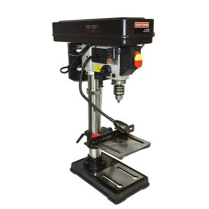
You do not need a drill press, but it makes many things easier. A drill press is more stable than a handheld drill and easier to setup for repeatable depth or consistent spacing. Drill presses are more powerful than handheld drills and have more settings for speed, both useful features when using different types of bits and materials.

Limited throat depth is a disadvantage of the drill press. A press advertised as “10 inch” swing or throat depth can drill to the center of a 10 inch piece of material. This means the distance between the chuck and the vertical support is 5″. In my experience, 10 inches is the minimum size press that will be practical with tube amp top plates. Even better if you can fit a 12 inch or larger in your budget and work-space.

Drill presses work best on flat stock. While this isn’t necessarily a disadvantage, it is something you need to plan for while building enclosures. Drill first, then glue and assemble!

In most cases a press is slower to setup for cuts than a hand drill. I still have a good quality battery powered handheld drill when I just need a quick hole for mounting bolts/screws, when placement isn’t critical, or when I don’t have clearance to use a press.

Drill Bits

drill bit pilot point

You don’t need anything super fancy or expensive for drilling in wood and aluminum, but you should invest in a decent set of bits. Regular twist bits with a pilot point have worked great for me in both presses and hand drills. The narrower end on a pilot point also helps with hole placement when cutting to precise locations on the press. I suspect that brad point bits would not hold up well to lots of aluminum/metal drilling and I’ve broken a lot of cheaper standard point steel bits. A bit set with a good coating on it will definitely stay sharp longer.

Bi-metal Hole Saws

holesaw

For cutting out socket holes and holes for mounting large capacitors, I use bi-metal hole saws. I’ve tried punches, but I like working with 1/8″ aluminum and I haven’t found a punch that works for this thicker material. If you’re working in thinner steel, a good set of Greenlee punches may be your best friend.

I cut octal holes with a 1 1/4″ hole saw and 9-pin holes with a 3/4″ (sometimes it’s necessary to enlarge this to 7/8″ depending on the socket and tube). Both of these sizes will work with a handheld drill, but larger sizes for motor run caps really beg for a drill press.

I’ve been very impressed specifically with the Milwaukee Hole Dozer series. They’re easy to find at the big box home improvement stores, the arbor can be swapped between saws, and they’re easy to clean out shavings and stuck plugs. I’ve drilled a lot of octal socket holes without serious dulling of the saw.

Unibit

unibit

Unibit is your BFF for drilling out grommet holes to run transformer wiring. It is also very handy for a quick 9-pin socket hole. I’ve found the 7/8″ size to be perfect for most tube amp needs (anything bigger than this is a hole saw job). Tip: use painters tape to mark your depth on the bit so that you don’t overdrill to the next size larger than intended.

The unitbit has a tendency to grab the stock you’re drilling into. Whether using this with a handheld drill or a press, be sure to super clamp your stock and avoid spinning top plates of death.

Unibits bits aren’t cheap, but they’ll last forever if you get a good quality one.

Countersink Bit

countersink

This one isn’t the most used bit in my toolbox, but I do think it adds a nice touch for top plates. I use these to put the head of mounting screws level with the top plate and to clean up any holes drilled for chassis air flow. These work on wood and aluminum.

Forstner Bit

forstner

The forstner bit is your hole saw equivalent for wood work. A forstner bit allows you to drill circular holes in wood, removing the material to a specific depth. Most jacks and pots do not have much of a bushing on them. If you want to mount jacks and controls in the wooden portions of your chassis, you’ll probably need something like this to reduce the wood to a manageable thickness:

IMG_20171022_125533053.jpg

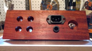
I use forstners to remove wood from both the inside and the outside of my enclosures, depending on where I want to locate the recess. A good forstner bit leaves a very clean edge so I use them wherever possible in wood. Don’t try these in aluminum.

Jigs

Because I incorporate solid state parts on heatsinks in many of my builds, I drill a lot of holes to vent the chassis:

A thin and flat ruler taped to a straight fence makes a really simple and useful jig for making sure the hole spacing and placement is consistent on the drill press. Pictured below:

IMG_20180902_141052248.jpg

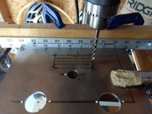
  • First, layout the lines along which you’d like to drill the holes in your plate with a square and a permanent marker (remember to use the mirror image if marking on the underside of the top plate).
  • Second, mark your material along the edge using a square. Exact location is somewhat arbitrary.
  • Now, line up the material and bit to cut the initial hole at your desired starting location (but don’t drill yet).
  • Adjust the fence to line the mark on the material’s edge up with any whole inch mark on the fence/ruler (you see the marked line at the 10″ spot on the ruler in the photo). The material should be flush against the fence at this point.
  • Finally, clamp the fence/ruler combo down securely and recheck that you are drilling the first hole where you want and that the mark on the material’s edge is lined up with a convenient mark on the ruler.
  • Now you can drill the first hole and move the material along the fence to keep the rest of the holes in a perfectly straight line. Using the mark on the edge and the ruler, you’re able to very precisely control the distance between holes.


One little project comes to fruition

Early this year, I wrote a post about simple RIAA correction with opamps. Although it doesn’t involve tubes (yet), I recently completed a PCB-based build based on this post. This was both to test the calculations/theory as well as good practice in PCB design.

This ultra-simple phono preamp runs on just a pair of 9V batteries for power and utilizes a mix of feedback and passive EQ for RIAA correction. The batteries should last about 24 hours (playing time), but a bipolar AC-derived supply could be substituted without trouble. Gain is easy to adjust with just a couple of resistors (set at 40db in my build). The bill of materials runs about $25 with 5532 opamps and 5% tolerance WIMAs.

I’m planning on building a couple of these with coworkers and basing build instructions and any revisions on the experience. I do have some extra boards from this first run. Shoot me an email if interested!

A different way to RIAA

Phono preamps can be tricky builds due to the need for high gain with low noise. In tube land, linear high gain is not too difficult to achieve even without feedback. Power-supply-based noise can often be brute forced with extra filtering, actively regulated B+, and/or DC-powered tube heaters. High PSRR topologies (eg differential) also have an advantage in the early amplification stages.

stop stop its dead already.png
building phono PSUs be like

The place where most DIY builders are probably tripped up is the mysterious RIAA voodoo.  Because the physical limitations of the vinyl medium and cutting process require a limiting of low frequencies and a boosting of high frequencies, we need to reverse this EQ on the playback end in order to get back to ‘flat’ frequency response.

At it’s most basic, the RIAA equalization standard defines three frequencies: 50hz, 500hz, and 2122hz. We should have a 20db boost to 50hz, a -20db/decade transition from 50hz to 500hz, flat playback from 500hz to 2122hz, and a -20db/decade falling response above 2122hz. Note that 20db/decade is equivalent to 6db/octave, so these are not especially steep filters.

Splitting the RIAA requirements between low (<1khz) and high (>1khz), the low frequency manipulation requires at least 20db of gain from whatever device we are using. This type of EQ is commonly referred to as a shelving filter. The high frequency portion is only reducing the response and so it doesn’t require gain (ignoring the overall gain needed to get to line-level signals). This reducing of the high frequencies can be as simple as a first order low pass filter (just a resistor and a cap).

Tubes, with their fairly high output impedance and finite Mu, complicate RIAA frequency-dependent impedance calculations. Operational amplifiers, on the other hand, make filter maths fairly straight forward. Here’s an example:

opamp riaa

Starting at the output, the R1 and C1 combination form a simple low pass filter. Because the output impedance of opamps is so low, our equation need only involve the cap and resistor:

f(-3db) = 1,000,000 / (2 * Pi * CuF * R), rearranged as:

R1 = 1,000,000 / (2 * Pi * 2122hz * C1uF)

Begin with a tight tolerance capacitor (say 0.1uF) and you’ll get a resistor value that may come off the shelf or be created with a parallel/series combination (in the case of a 0.1uF C1, the resistor would need to be 750 ohms). The resistor appears in series with the output, so large values may require a high input impedance in the following stage.

The shelving filter created by R2, C2, and R3 appears in the feedback circuit of the opamp. Because we need 20db of gain, we know that the ratio of R2 to R3 should be approximately 10:1 (a 10x voltage gain difference corresponds to 20db). The 50hz point is set by the combination of R2 and C2 and is found with the same kind of capacitor reactance equation as the low pass:

R2 = 1,000,000 / (2 * Pi * 50hz * C2)

Again, start with the cap value because caps have fewer options and are harder to find in a tight tolerance. A 0.047uF cap gives an R2 of about 68k, meaning R3 should be about 6K8. The overall gain of the stage is further set by R-gain (Av = 1 + R3/R-gain).

So that’s a pretty simple way to EQ your vinyl to flat. More gain to bring the signal up to line level could be added by following the EQ/opamp stage with a ‘normal’ tube stage or two. Expect to see some more on this topic in a future project!

Board prototypes on the way

Although I love wiring tubes point to point, there are times where some TO92 or other small parts are needed. These often benefit from short leads, making layout and spacing critical. One of my upcoming projects makes these kinds of demands. Having dealt with death-by-soldering iron and oscillations when trying to point to point wire small parts in the past, I decided to try my hand at some small boards to make things easier on myself.

I still believe that for tubes there are real advantages to p2p wiring and turret strips. After all, they’re fairly large robust parts and part of the fun of building something is scavenging enclosures, optimizing the layout and grounding, etc. But where a small solid state circuit is needed, a modular board is great to have.

More to come on these boards once I’ve been able to test them and use them in builds.

ccs board finalreg board finalshunt board final