For the current project (a line stage with added phono) I needed more than one B+ value. The difference between the two voltages I wanted and current drawn was too large for a single high voltage rail and a filter or regulator to drop the lower rail to the correct value. So I looked for ways to add a voltage doubler to a standard bridge rectifier. Turns out, there’s more than one way to skin a cat:
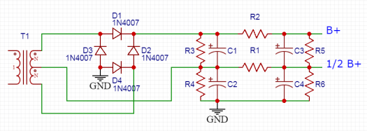
The “Millet Doubler” is detailed here and uses a single center-tapped winding. The entire secondary is rectified via a bridge rectifier, rather than the usual approach of grounding the CT and using a full-wave rectifier. The center tap voltage is then rectified and feeds the lower half of a stack of capacitors.
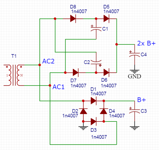
The “TubeLab Doubler” is something I found posted on diyaudio.com; it is also discussed in depth here. This one uses a single winding without a center-tap. The doubled voltage rail is somewhat lower than what you’d get in the Millet Doubler, but still potentially useful especially with inexpensive isolation transformers.
I can only find a schematic of the “TubeCAD Doubler” (no discussion), but if you’re familiar with TubeCAD’s blog, it doesn’t look too unfamiliar. See a good article on multiple power supply voltages here. This one looks a little bit like a combination of the other two variations.
In the end I went with the second version because it allows me to use an isolation transformer (and because I found it before seeing the TubeCAD one). Of course a couple of wiring oopsies are being worked out before I can report back on the power supply or preamp it is intended to feed…
A recent discussion on diyaudio.com reminded me of the opamp-based RIAA idea I shared last summer. It turns out that someone else has done something similar and reports very good results. Koifarm was after a more integrated build with phono, streaming, and line level all in a box, but the basic idea of using an opamp to perform the RIAA corrections and a tube to provide some/all of the voltage gain is the same. We differ just in how it’s integrated: I’m after a simple RIAA module with outboard tubes while Koi was going for an all-in-one.
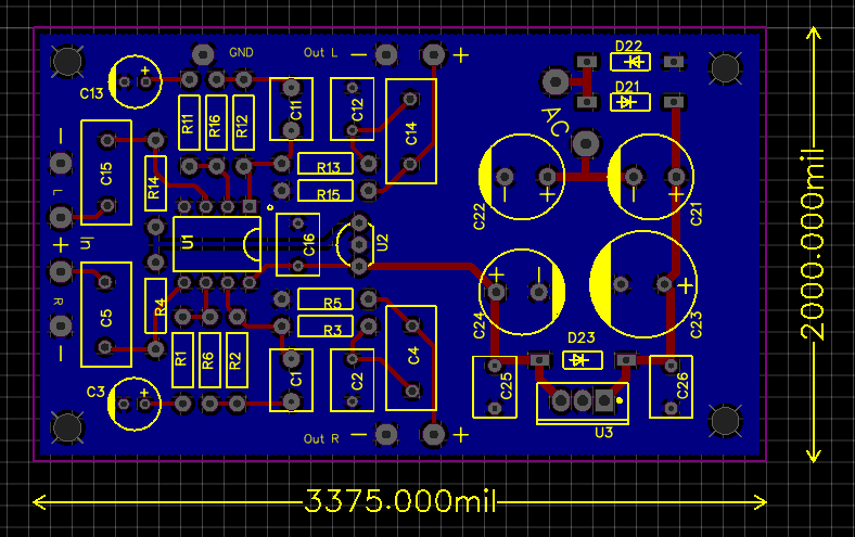
Here’s where I’ve landed so far on a board to contain the opamp bits and bobs:
The opamp runs from the 6.3Vac heater winding that would be included on any tube-centric power transformer, meaning there are no special windings or an extra transformer to power the solid state section. The output of the RIAA module would be fed to a simple tube gain stage of your choice. Here’s a grounded cathode application, but keeping the tube off the board means there’s tons of flexibility.
So, will it work? Koifarm thinks so and he’s a pretty prolific phono preamp builder. I’ve also already tested the same RIAA correction scheme in the battery powered phono project. I’m saving up a few designs to place a board order, but I’m hoping this RIAA module would make for a relatively simple and fun build this year.
Phono preamps can be tricky builds due to the need for high gain with low noise. In tube land, linear high gain is not too difficult to achieve even without feedback. Power-supply-based noise can often be brute forced with extra filtering, actively regulated B+, and/or DC-powered tube heaters. High PSRR topologies (eg differential) also have an advantage in the early amplification stages.
building phono PSUs be like
The place where most DIY builders are probably tripped up is the mysterious RIAA voodoo. Because the physical limitations of the vinyl medium and cutting process require a limiting of low frequencies and a boosting of high frequencies, we need to reverse this EQ on the playback end in order to get back to ‘flat’ frequency response.
At it’s most basic, the RIAA equalization standard defines three frequencies: 50hz, 500hz, and 2122hz. We should have a 20db boost to 50hz, a -20db/decade transition from 50hz to 500hz, flat playback from 500hz to 2122hz, and a -20db/decade falling response above 2122hz. Note that 20db/decade is equivalent to 6db/octave, so these are not especially steep filters.
Splitting the RIAA requirements between low (<1khz) and high (>1khz), the low frequency manipulation requires at least 20db of gain from whatever device we are using. This type of EQ is commonly referred to as a shelving filter. The high frequency portion is only reducing the response and so it doesn’t require gain (ignoring the overall gain needed to get to line-level signals). This reducing of the high frequencies can be as simple as a first order low pass filter (just a resistor and a cap).
Tubes, with their fairly high output impedance and finite Mu, complicate RIAA frequency-dependent impedance calculations. Operational amplifiers, on the other hand, make filter maths fairly straight forward. Here’s an example:
Starting at the output, the R1 and C1 combination form a simple low pass filter. Because the output impedance of opamps is so low, our equation need only involve the cap and resistor:
Begin with a tight tolerance capacitor (say 0.1uF) and you’ll get a resistor value that may come off the shelf or be created with a parallel/series combination (in the case of a 0.1uF C1, the resistor would need to be 750 ohms). The resistor appears in series with the output, so large values may require a high input impedance in the following stage.
The shelving filter created by R2, C2, and R3 appears in the feedback circuit of the opamp. Because we need 20db of gain, we know that the ratio of R2 to R3 should be approximately 10:1 (a 10x voltage gain difference corresponds to 20db). The 50hz point is set by the combination of R2 and C2 and is found with the same kind of capacitor reactance equation as the low pass:
R2 = 1,000,000 / (2 * Pi * 50hz * C2)
Again, start with the cap value because caps have fewer options and are harder to find in a tight tolerance. A 0.047uF cap gives an R2 of about 68k, meaning R3 should be about 6K8. The overall gain of the stage is further set by R-gain (Av = 1 + R3/R-gain).
So that’s a pretty simple way to EQ your vinyl to flat. More gain to bring the signal up to line level could be added by following the EQ/opamp stage with a ‘normal’ tube stage or two. Expect to see some more on this topic in a future project!
Here’s a spreadsheet I built for calculating RIAA values in two stage tube phono preamps. When comparing results to other published designs using the same filter network, everything looks correct (within a few percent due to estimation of Rp). I used this sheet for El Matématico.
If you want to estimate values for something like a CCS loaded stage, you can set Rload on the appropriate stage to 1M or thereabouts. If you’re looking at using a cascode, mu follower, SRPP, etc 1st stage, you’ll need to make sure the Zout figure the sheet uses (cell I6) reflects the Zout of the topology because it is used to calculate R1. Same thing goes for cell I3 (Miller capacitance of 2nd stage) if you use a gain stage after the filter that affects this (cascode, grounded grid, etc).
Not long ago I wrote a short post about MC carts and the noise contribution of tubes when amplifying such tiny signals. I focused on step-up transformers as the solution to noiseless amplification, but there is another approach. If you don’t like solid state, stop reading. Ok, now that you stopped reading and checked out the going prices for step-up transformers, you’re back. Good. Don’t worry, this approach uses the tubeyist solid-state device: the JFET.
A cascode is a compound amplifier in a totem pole arrangement. Here’s a great explanation by Valve Wizard Merlin. This allows you to achieve huge amounts of voltage amplification with fairly economic current usage and without coupling capacitors or multiple phase inversions. The driving force in this arrangement is the transconductance of the lower tube. The lower tube and upper tube do not need to be the same, nor do they even need to be the same type of device.
JFETs (junction gate field effect transistors) are voltage controlled devices, just like tubes. In fact, they bias in a very similar way: Rsource in the above raises the n-type JFET’s source voltage above the gate, similar to the way a cathode resistor in a grounded cathode amplifier raises the cathode above the grid. On the other hand, even the lowliest JFETs have a higher transconductance (gm) than the mightiest small-signal tubes. Icing on the cake is that JFETs, properly chosen and cared for, are lower noise devices. As such, they make a great lower device in a hybrid cascode.
The overall gain of a cascode simplifies to approximately:
gm(lower) * Rload
This equation is a simplified expression of the total gain of both devices:
AKA [JFET gm * load divided down at tube’s cathode] * [grounded grid gain of tube]
Rp and Mu are characteristics of the tube upper device. The choice of upper device affects how much of the voltage gain is performed by the JFET by affecting the load it sees. A high Mu and low Rp upper tube (i.e. high transconductance) presents a lower load as divided down at its cathode, thus less voltage amplification by the JFET (and more voltage amplification made up by the tube due to the higher Mu). A low transconductance upper tube does the opposite. But regardless of the tube (assuming an appropriately sized Rload), the overall gain remains the same: ultimately the transconductance of the JFET multiplied by the load on the upper tube.
So where’s this headed? Obviously there’s a full design coming to try out this idea, but the takeaway is that a hybrid cascode is potentially a great way to step up the tiny signals from a moving coil cartridge with very low noise and hand the now-larger signal off to a tube amplification stage without multiple supply voltages, coupling caps, or an expensive step up transformer.
The catch? Cascodes have poor power supply noise rejection and a fairly high output impedance. But there are ways to minimize these factors, too.
I haven’t built an all-tube MC phono preamp. I build MM stages with the assumption that MC users will use step up transformers. Generally, its much easier to keep the whole thing quiet that way. This is a simplified explanation, but I hope it gets the general idea (SNR) across:
Tubes impart noise in a few ways but they’re all usually tiny. MC carts need around 60-70db of gain to bring them up close to line level. This is multiplying the MC signal from the cart by 1000-3000x before it gets to your amp. In contrast, a MM cart usually needs 40-50db, which is an amplification of 100-300x.**
The more tubes used, the more very tiny sources of noise get introduced. Although the noises are tiny, they are amplified by the preamp, just like the signal. So the more gain required to get the signal to a desired listening level, the closer the tiny noises get to being audible as well. Several stages of tubes for a very large amount of gain can lead to unwanted noise for this reason (guitar amps and phono preamps are both good examples of this).
The step up transformer cannot practically do more than about 20db-25db of gain without having some undesired consequences, but they don’t have ‘moving parts’ and are very good at rejecting noise/hum. The 25db of gain from a transformer is enough to lower the tube gain needed from 3000x (70db) to 175x (45db), meaning any noise from the tubes is amplified much less. It’s kind of like giving the tube part of the preamp a head start in the race against noise.
So that’s why I haven’t built a MC phono preamplifier. If I were to build one, I’d most likely add step up transformers to a MM preamp like the El Matematico or similar. To me, this is the most practical approach with the highest likelihood of success.
**At the risk of muddying the waters, phono preamps actually need about 20db more than the numbers mentioned here but this is then attenuated by the RIAA correction filter to result in ~40db or ~60db net gain, MM and MC respectively.