Multiple B+ voltages from a single transformer winding

For the current project (a line stage with added phono) I needed more than one B+ value. The difference between the two voltages I wanted and current drawn was too large for a single high voltage rail and a filter or regulator to drop the lower rail to the correct value. So I looked for ways to add a voltage doubler to a standard bridge rectifier. Turns out, there’s more than one way to skin a cat:

The “Millet Doubler” is detailed here and uses a single center-tapped winding. The entire secondary is rectified via a bridge rectifier, rather than the usual approach of grounding the CT and using a full-wave rectifier. The center tap voltage is then rectified and feeds the lower half of a stack of capacitors.

The “TubeLab Doubler” is something I found posted on diyaudio.com; it is also discussed in depth here. This one uses a single winding without a center-tap. The doubled voltage rail is somewhat lower than what you’d get in the Millet Doubler, but still potentially useful especially with inexpensive isolation transformers.

I can only find a schematic of the “TubeCAD Doubler” (no discussion), but if you’re familiar with TubeCAD’s blog, it doesn’t look too unfamiliar. See a good article on multiple power supply voltages here. This one looks a little bit like a combination of the other two variations.

In the end I went with the second version because it allows me to use an isolation transformer (and because I found it before seeing the TubeCAD one). Of course a couple of wiring oopsies are being worked out before I can report back on the power supply or preamp it is intended to feed…

2019 NAMM Show Transformer Stuff

This was a busy week, so all I have to post is a couple of quick pics of people I chatted with at the NAMM show in Anaheim (which I attend for my day job).

Kevin from K&K Audio was hanging out in the Lundahl booth on Saturday morning before the show. We chatted about the state of DIY, local building groups, and the NAMM show. I had never met Kevin before but we had an immediate connection over the DIY hobby. K&K is the USA distributor for Sweden-based Lundahl Transformers. Their C-core construction, multiple winding configurations, and super-detailed datasheets are unique in the tube building hobby. Lundahl products are also sought after for studio and pro line-level applications and microphones (hence the NAMM booth).

I also found a booth for Triad Magnetics at the show this year! This was the first time I’ve seen Triad at NAMM and I had to say hello and thank them for manufacturing such affordable and easy to source power supply chokes (which I use in almost everything I build). The Triad team said the show was going well and that they’d probably be back next year.

I had a whirlwind NAMM schedule this year and didn’t get to spend any real time at tube booths like JJ Electronics or Electro Harmonix. I did take some time to get scanned for CIEMs at Ultimate Ears, though. There may be a portable amp project somewhere in the future…

New page: grounding

If you didn’t already catch it, I’ve added a page to the power supply section on grounding. This is a hard topic to do justice because there is no one approach, there are just approaches that work for individuals/projects. I try to give a rough outline of my thought process and strategy for grounding projects on the new page.

Here are a couple of other good reads on the topic:

David Davenport “Audio Component Grounding and Interconnection” on diyaudio.com

Bruce Heran “Grounding and Shielding for your DIY Audio Projects” on diyaudioprojects.com

Letters to WTF: What kind of rectification am I supposed to use with this power transformer?

I was helping someone with an amp build over Telegram (chat app) yesterday when this question came up. He had in fact been trying to use a diode bridge with a center tapped transformer with both the center tap and the bridge grounded. He released the magic smoke from his transformer, though there were a couple of other issues that may have contributed to this.

When I was starting out, I had some confusion with power transformers and rectifiers, too. Probably like many others, I started with small solid state circuits, where center tapped transformers are rare. Once I started building with tubes, the secondary ratings of center tap transformers were another source of confusion. So here’s a by no means complete rundown of transformer configurations.

1. My transformer doesn’t have a center tap and I want a full-wave rectified DC output.

You want to use a diode bridge (figure 4-8). This is four diodes arranged to rectify both positive and negative phases of the power transformer’s AC output. Your ground will be taken from the bridge, NOT THE TRANSFORMER. This ground at the junction of the diodes creates a return path for current that ‘switches’ with the changing phase of the secondary’s AC output.

2. My transformer has a center tap and I want a full-wave rectified DC output.

You want to use a “conventional” full-wave rectifier (figure 4-5A). This requires only two diodes (solid state or a rectifier tube). Your ground is taken from the center tap of the transformer (which is then the return path for current). Many center tapped transformers are rated as the full end-to-end secondary voltage. For example, a 300VAC center tapped secondary would actually provide 150VAC into a conventional full-wave rectifier. You’ll sometimes see the same transformer listed as 150V-0-150V.

Here’s a great clarification of what’s going on with full-wave bridges and conventional full-wave rectification.

How much voltage do I get?

With either of the above, the unloaded DC output into a capacitor-input filter is approximately the AC output from the secondary times the square root of two, minus the voltage drop across the diodes (minimal for solid-state, can be considerable for tube rectifiers). Into a choke-input filter (unloaded, ignoring diode drop), the output will be approximately two times the square root of two divided by pi (about 0.9) of the AC output of the transformer secondary.

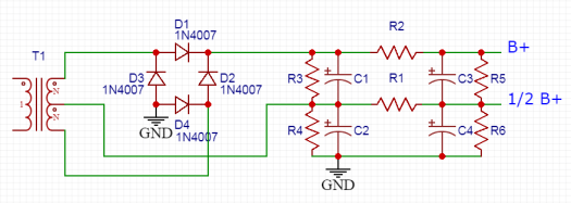
3. My transformer secondary has a center tap, but I want a bipolar power supply.

Here you can combine the center-tapped transformer and the aforementioned bridge style rectifier. See figure 5.1c here. This creates two separate full-wave rectified voltages, one positive and the other negative with respect to the center tap. If you read a lot of TubeCAD, you see bipolar tube circuits pretty regularly.

4. My power transformer is 300VAC (150V-0-150V) center tapped, but I want 400VDC!

Another way to combine the center tapped transformer and bridge rectifier is to ignore the center tap altogether. Do not connect it to ground; just SAFELY tape it off and tuck it away. Now you have basically a non-center tapped transformer and you can treat it like number 1 above. Note that current capacity in this configuration is typically half of what the transformer was originally rated for.

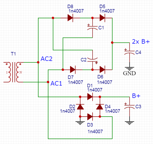
5. My power transformer is 120VAC without a center tap and I want 300VDC!

To achieve this, you can use a voltage doubler (see figure 4 “Delon circuit). This requires two diodes and two capacitors. Because the capacitors will see large pulses from the diodes and will be supplying the rest of the circuit continuously, they need to be a fairly large value. But because each only sees half of the supply voltage, their voltage ratings are a little more relaxed in comparison to what is required in a filter. The unloaded DC output into a capacitor-input filter is approximately twice the AC voltage from the transformer secondary times the square root of two. Current capacity must be de-rated at the output voltage by a factor of at least two.

6. My power transformer has dual matching secondaries and no center tap. What do I do?

This is common with toroidal power transformers in particular. You can wire the two secondaries in parallel (making sure the polarities are matching) and use a bridge rectifier like number 1 above. The AC output of the transformer will be the same as either secondary by itself (and current capacity will be doubled). You can also wire the secondaries in series by connecting a positive and negative from each secondary (not the positive and negative from the same secondary!). This creates a center tap at the junction. The AC output end-to-end will be twice the AC output of a single secondary if the secondary is not grounded (see number 4 above). If you ground the secondary you created, you can use a rectifier like number 2 above.

New Project: La Luciérnaga (PSU)

This write-up will have two parts.  The first (the PSU) is posted and hopefully I’ll have the amp write-up done shortly.  This project is the most ambitious one I’ve written up for the site so please excuse the omission of some of the finer calculations and details.

Although the power supply is rather complicated, the amplifier will be pretty straightforward (pinky swear). The supply can be used with other amps and the amp can be used with other supplies, which is one of the reasons I decided to split it into two pages.

Click here to descend into the madness!

Letters to WTF: rectification

Q:

What is your opinion on rectification?

A:

Tube vs SS rectification is a hotly contested topic in the audio world and what I tell you will be opinion.  That said, I’ve used both and never had a problem (eg here, here, here, here).  When designing from scratch, my choice is dictated by my power transformer, space available on the chassis, and whether a tube rectifier is in the budget. Sound quality is not really a consideration.
­
 ­
Of all the parts in a Class A single-ended amp that contribute to the sound, I think rectification is one of the least important. If you end up with the right B+ voltage and you filter it so that there is no ripple, you’re 99.9% of the way there. The debate about tube vs SS rectification usually focuses on theoretical advantages or disadvantages without respect to whether a supply is well-designed and implemented.
 ­
All things being equal, and space and budget allowing, I tend towards tubes because I like the way they look and I like knowing that the high voltage will start up just a little bit slower. All things being equal, others would go for solid state because it has a lower output impedance and allows for larger filter capacitors.
 ­
There’s more emotion than measurement in either decision.
 ­
274B borrowed from thetubestore.com and 1N5408 borrowed from PartsExpress.com. I claim Fair Use here and anyways they can get bent if they don’t like me linking to them in exchange for the pics.