Bad Hombre tube headphone amplifier in the wild

I recently received some pics from W of a Bad Hombre Mk2 build (12AU7 + ECC99). This one uses Lundahl LL1676 input transformers and LL2765 output transformers, and features a regulated B+ and a loaded front panel of controls. Very nice!

The LL2765 is a fine transformer with ECC99 output tubes in this circuit. It has a 5k primary and multiple output taps for 32, 150, 600 ohm headphones. The 5k primary will result in more power than the 8k in the original design, but it can also be used to reflect a higher impedance depending on what taps and headphone load one chooses (e.g. 300 ohm headphones on the 150 ohm tap for 10k load).

On a side note, I see Lundahl also now has a LL2774 3k primary headphone output transformer (16, 64, 300 ohm secondary taps). This is a very similar turns ratio but it looks like the LL2774 is available with a bigger gap in single-ended configuration for higher current output tubes. Great to see new options for headphone output transformers!

Modern Quality Amplifier Conceptual Outline

May is a very busy month for me personally so I have only a short update this week. My last post was about the Quality Amplifier, a forerunner to the well-known Williamson amp. I proposed a modernized 6V6 A2 version based on the same topology that could probably crack double digit power.

In the conceptual outline above we have a MOSFET rather than a tube as a concertina splitter to save heater power. The unity gain MOSFET splitter feeds a tube differential pair to generate enough voltage gain to drive the outputs. MOSFET grid drivers with a CCS load help the differential stage cope with the drastic impedance changes at the output tube grids in A2 operation. Outputs are wired as triodes, of course.

The A2 drivers will go on a PCB. I also have one designed for the MOSFET splitter, though that’s simple enough to wire any way you might want. We’d need just three tubes per channel: a pair of 6V6s and a dual triode driver. My driver pick at the moment is probably the 5965 (or a pin-compatible 12AT7 if it needs to be new production).

I’m also happy to report that progress is being made on the preamp project. Hopefully I’ll have pictures to start sharing in the very near future!

Los Monos are coming

Here’s a sneak peak of the long-term push-pull project. The second monoblock is one cathode bypass capacitor away from being ready for playback. A bad tester tube took out the cap on one side during testing with a bang, but I’ll have replacements soon. Until then here’s the intro of the project write up.

The monkey on your back

Everything should be made as simple as possible, but not simpler.

-Einstein

There comes a time in every DIY builder’s life where he or she gets the urge to stretch beyond single-digit output power and single-ended amplification. There is no shortage of worthwhile projects to choose from: variations on Williamson, Mullard, or Dynaco push-pull topologies are easy to find discussed in forums and tweaked to compensate for modern parts. You can even find kits for something like the Dynaco ST-70.

When the double-digit power bug bit me I could not bring myself to abandon my usual no-feedback, triode output, class A comfort zone. This is the simplest (but not the only) path to good sound and my speakers are efficient enough. I’m also too lazy to do feedback math but that doesn’t mean open-loop, class A triode designs aren’t an engaging challenge. This build faced the following complications (which are common to many push-pull amplifiers):

  • Class A requires healthy current in the output stage: this needs to be balanced in the output transformer to preserve inductance
  • Two cascaded grounded cathode input stages is too much gain, but one stage is generally not enough
  • The input stage must have low enough output impedance to drive the triode output tubes

For the most part, my solutions to the challenges strive for simplicity. As is often the case in tubes and life, simplicity in some areas is traded for complexity elsewhere. This push-pull amp has only two stages, the outputs are cathode biased, and it requires only three tubes per channel. To make this seeming simplicity possible, I used solid state helper circuits on PCBs. While these helper circuits are not technically complex, they drive up the parts count and require some measurement and adjustment.

Here is the conceptual topology for Los Monos:

Pictured is a two-stage triode output push-pull amplifier. The output stage is garter biased and the voltage gain and phase splitter stages are combined in a folded cascode long tail pair. This is all described below with a full schematic (showing lots more parts).

More of this write-up is on the way as soon as I’ve got both channels playing and glamour shots are taken!

A Mighty Cacahuate caught in the wild

Student “D” sent me some pictures of his Mighty Cacahuate project with a twist and it’s too unique not to share. D developed a PCB for his build and mounted all the amplifier parts to a top plate as would usually be done. Instead of a boring wooden box, D dropped this into a boombox enclosure for all-in-one listening. I love to see the creative use of a basic schematic I posted here on my little website.

We initially troubleshooted some wiring over email, mostly due to my omission of the details of heater wiring and pin numbers on the original schematic. Once sorted though, D says the amp started playing and sounding great without a hitch.

It was an amazing feeling the first time they powered on.

-D

Careful there, D, that feeling is habit forming!

Update on the mono-blocks: left channel is done and right channel is coming together quickly. Write-up for the project is also underway. Looking forward to playing in stereo!

EL34 tester tubes, also considering springing for KT88s on this project
Night shot. Red glow through the vents is LEDs used as voltage references in CCSs inside.

2018 year in review

I can’t for the life of me remember a louder year than the one that ends next Tuesday. Personally, professionally, politically, it was a hectic twelve months. In retrospect, concrete and measurable goals (AKA resolutions) are probably what kept me alive and sane amidst the chaos. I’m no self-help guru or productivity genius, but I feel like I have survived a sink-or-swim situation over the past year, so I’ll share some thoughts on living with a hobby in the real world. First, I’ll pat myself on the back for my accomplishments:

Finish master’s degree:

  • Done! The last year and a half were a challenge (my daughter was born spring of 2017), but I somehow found the energy, motivation, and focus needed to finish my MBA. I hope that being done with school will now free up the mental space for other parts of life (family, friends, projects).

Post to blog every week:

  • 99% successful! I missed one or two weeks and not every post was laser-focused on tubes, but I’m happy that the blog and website survived a hectic year for me.

Exercise regularly:

  • Exercise is an important ingredient for mental focus for me personally. I also have my exercise equipment in the same room as my electronics workbench and the multi-tasking kept audio projects moving forward (albeit slowly). My explicit goal for this year was to get into the 1,000lb club (weightlifting) and I did it with some room to spare.

I’m a big fan of quadrant prioritization to keep daily life in perspective (this idea is credited to Eisenhower, I believe). The gist is that we should rank our goals as high/low importance and high/low urgency and pursue them accordingly. I draw one of these diagrams at least once a week:

If we spend our time in quadrants I and II, we’ll get the important stuff done. The hard part is understanding your goals well enough to see the difference between urgency and importance. There is plenty of subjectivity to this importance/urgency classification and not everyone would come to the same conclusions.

For me, tube projects are a solid quadrant II item and that isn’t going to change this year. However, being done with school now means that high urgency and high importance things are screaming a little less loudly. That lets me spend a little more time on long-term goals.

This is all just a long way of saying that I intend to build more this coming year. On the short list are:

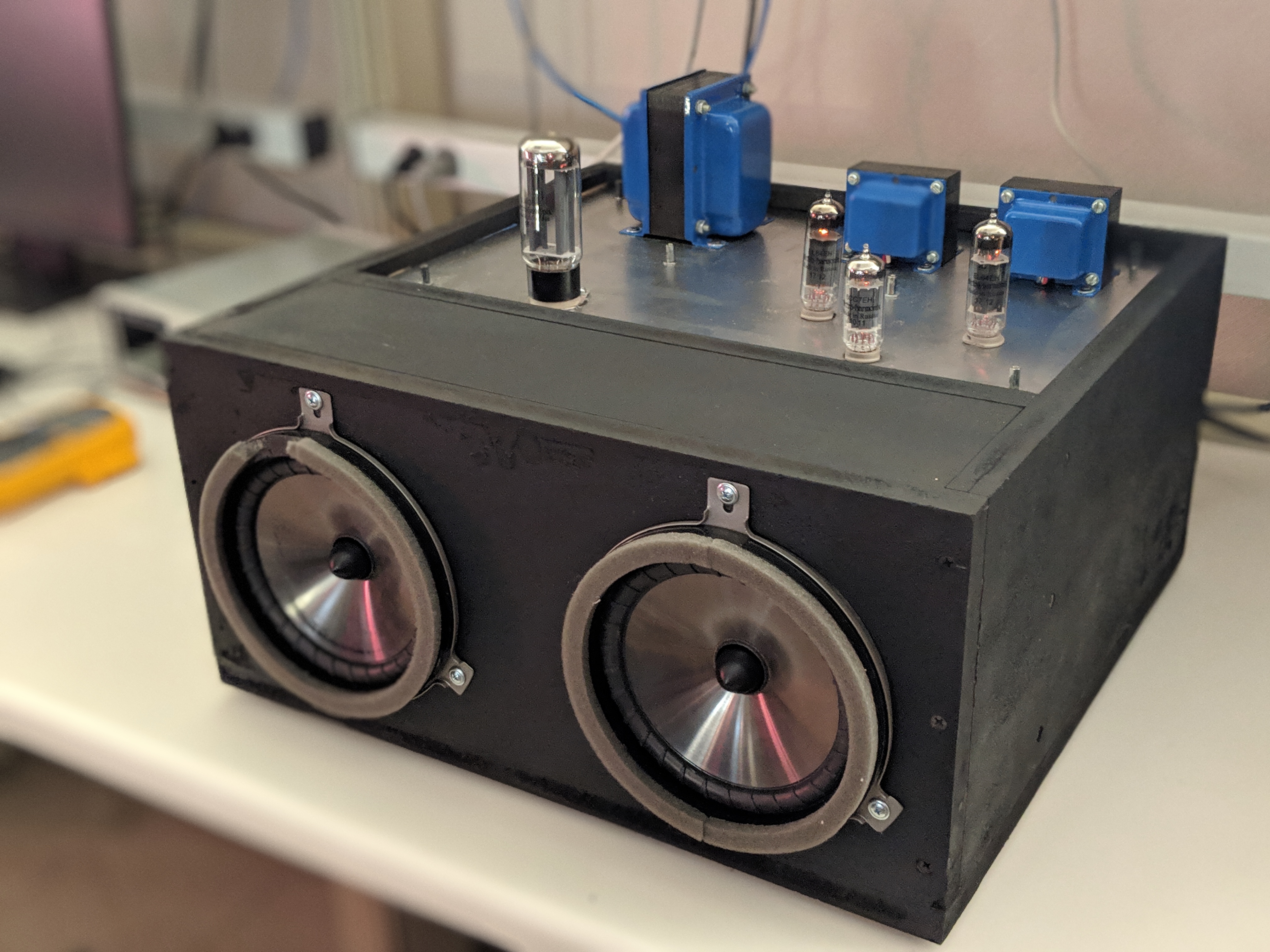
  • EL34 push pull mono-blocks (see pic for one very near completion)
  • Transformer-coupled line stage (to pair with above, probably DHT)

And on the list of schematics-in-waiting are:

  • EL84 push pull stereo amplifier
  • Line stage with integrated phono
  • SMPS-powered 6V6 SET headphone amp
  • Battery-powered experiments

On top of the workbench and test equipment projects that builds usually create, I’ll be happy if I can finish four of the above in 2019. I’d really like to return the website to its roots as a practical resource for projects and reading for beginners in the tube audio hobby. As I told someone else recently, my goal with this is creating the resources that didn’t exist when I started in the hobby. While this may not be urgent, it is important!

Solid State Phase Splitters

The phase splitter is a critical step in a push pull (differential) amplifier. Because tubes don’t come in “p-types”, we feed the output devices signals that are inverted relative to one-another in order get one to push while the other pulls.

I’ve been finding solid state concertina-style phase splitters crop up here and there recently. A couple of days ago even the great Pete Millett got in on the action. Millett employs a JFET concertina splitter in his hybrid amp (a must-read, btw), but MOSFETs are also a good option for this application if you use parts with reasonable input capacitance.

Here’s a push pull schematic I’ve been marinating that illustrates the MOSFET concertina:

mosfet concertina pp

By using the MOSFET we’ve reduced the twin-triode count in a stereo push pull amp by one. The MOSFET will also let the splitter swing closer to the power rails, though in this particular case the 10BQ5 doesn’t really need a lot of voltage swing at its grid. The tubes shown are odd heater standards: 407A is 396A with a 20V heater and 10BQ5 is 6BQ5 with a 10V heater.

You can find a lengthier explanation of the RC step network between the 407A and MOSFET in Morgan Jones or buried in this diyaudio thread. In brief, the resistor divider sets the DC voltage at the gate of the MOSFET while the 0.1u cap bypasses the upper portion of the divider at AC frequencies so that we don’t lose any gain due to the divider.

Big PP problems

approximate top plate.png

Hoffman’s Iron Law impacts all systems, regardless of the type of amplifier. It states that speaker designers may only optimize for two of three performance goals: efficiency, size, and frequency extension. Modern speaker design goals trend towards slim and minimally-intrusive boxes. Because few are willing to give up low frequency ability, this aesthetic trend has resulted in lower-efficiency speakers, requiring ever more powerful amplifiers.

When you have a set of bookshelf speakers or less-efficient towers, a single-ended triode amplifier may not cut it for power. Larger push pull (and parallel push pull) amplifiers are capable of using lower turns ratio output transformers and delivering more power to a load. That could be the difference between realistic dynamics and a more compressed musical presentation. Of course, there are some things to overcome when you upsize your tube amplifier.

  • The power supply – If building an amplifier with (parallel) push pull power tubes, you’re going to need a lot of heater current. You’ll also need a lot of high voltage current. This means solid state rectification is the way to go. Using a bridge rectifier (four diodes) rather than a full-wave (two diodes) also saves some efficiency in the transformer.
  • Size and weight – More current demands from the transformer(s) directly translates to a larger size and weight. Again, bridge rectifiers will help reduce the power transformer size slightly. A switching buck converter for heaters is also something worth looking into for efficiency’s sake. Building as monoblocks is a good solution, but you’ll probably spend twice as much on chassis, power supplies, etc.
  • Current sharing – To keep standing DC currents from saturating the output transformer core, we want all our output tubes to share current equally (or at least balance per phase in each channel). Bias servos, Blumlein garter bias, individual fixed bias, and individual cathode resistors all have their advantages and disadvantages. Careful consideration here is key.
  • Driving Miller capacitance – With a bunch of parallel output tubes, the input and driver stages will need some grunt to keep Miller Effect from rolling off high frequencies. This is especially true if you’re driving triodes in the output stage. A follower of some type may be needed to ensure a low enough source impedance.

If you haven’t already gathered, I’m a bit preoccupied with how I’ll utilize the big old chassis I picked up recently. Clearly something large is in store. The present question is octals or DHTs and two or four output tubes per side. The chassis originally held some monstrous iron, so there’s space for just about anything.

room for activities.gif

Santa, the slave driver (and misc tube news)

IMG_20170825_073348746.jpg

Since May, the sun has risen and set on my beautiful baby girl. Daddy does not resent any of it for a second, but babies and the holidays make for slow progress on tube projects. I think my New Year’s resolution will be weekly posts, even if they aren’t all in-depth technical posts or finished designs.

I’m starting early because something that is [sadly] unusual has just occurred. Someone released a new tube audio kit/board:

I’ve used Boozhound Lab’s products in the past, but this is the first kit Jason has released for tubes. It’s a push-pull 6C45Pi amplifier that puts out about 6W. With just a pair of triodes sandwiched between input and output transformers, it’s also a minimalist’s wet dream (and similar to what I did with the Bad Hombre Mk 1 for headphones). I love it already and I hope it encourages people to pick up their soldering iron and bite the Edcor lead time bullet.

Jason has a great discussion of the design and building the amp here.

WTF Updates:

Chassis work for a TubeCAD headphone amp build is done: this will be a review and test of a circuit hack JB suggested (see SRCFPP), pretty paduak wood

Chassis work for a small SET amp is nearly done: this will be a published design, kind of a study in traditional cap-coupled single-ended amplifier design, goal of making this write-up very beginner friendly with a focus on applying fundamental concepts