
So many options so little time. On the other hand, if I stopped thinking and started building, I might be able to actually try one or two of these.
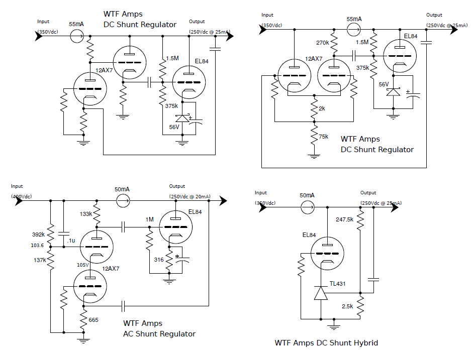
Upper left:
DC EL84 shunt regulator, output fed to a grounded grid amplifier (non-inverting), then to a cathode follower (non-inverting), then back into the shunt to amplify and cancel any power ripple on the output. A CCS feeds the shunting device to provide a high impedance.
Upper right:
Same shunting arrangement, now fed by a differential amplifier (non-inverting). You can think about the dif amp kind of like a cathode follower driving the cathode of a grounded grid amplifier. Weakness here is the high output impedance of the dif amp and low input impedance of the DC shunt (shunt could be switched to non fixed bias for a higher input impedance though, see next).
Lower left:
Auto-bias shunt (varies with wall voltage) fed by a cascode. The cascode is on the ‘other side’ of the CCS to take advantage of the higher B+ headroom. This will also introduce an un-wanted ripple signal, so the upper triode is configured for 1x gain (Ra = Rplower + [Mu + 1] * Rklower). Injecting the ripple through the voltage divider to bias the upper grid would, in theory, cancel the ripple on the ouput. The ripple we want comes from the output and is fed to the grounded grid lower triode in the cascode to be amplified as an error signal and fed to the EL84. Multiple feedback loops here, may not be stable.
Lower right:
For the iconoclasts, a TL431 in the cathode of the grounded-grid EL84 controls the current. The tube is really here just to protect the low voltage SS part from the high voltage output. A cap feeds the AC ripple from the output to the TL431.
