
Having found an irresistible deal on a pair of Hammond 1620A output transformers ($35 each), I have started some preliminary research on suitable amplifiers to build around them. These transformers have a 6.6k primary and are rated for 20W. This is around the power and impedance used in classic amplifier topologies like the Mullard 5-20 or the Williamson Amplifier. Both would probably provide blameless performance, but I’ve got this incorrigible itch to do things the hard way.
Dennis Grimwood’s website Optimized Electron Stream has a great collection of articles and reading. In particular, his history of the Williamson Amplifier caught my attention. According to Grimwood, the Williamson amplifier was an evolution of a design published as The Quality Amplifier in Wireless World in 1943 (and updated in 1946).
Note you can find the archive of Wireless World back issues here at American Radio History.
The Quality Amplifier was the work of WT Cocking (who was also a prolific writer about valve electronics). In contrast to other contemporary designs using interstage transformers, Cocking exclusively used RC coupling between stages and a concertina phase splitter at the input. Much time is spent in his Wireless World articles detailing the care and feeding of capacitors, something we take for granted today.
Several potential triode output stage configurations are detailed in the 1946 article:
- the original push-pull PX-4, producing 4W (or 8W with higher supply voltage)
- push-pull PX-25, producing 12W
- push-pull 6V6G triodes, producing 2W
All of the designs recommend MH4 valves in the phase splitter and driver stages, but list the 6C5 as an alternative. The 6C5 is a forefather of the modern 6SN7. None of the variations use global negative feedback. Here’s an example schematic showing the topology:
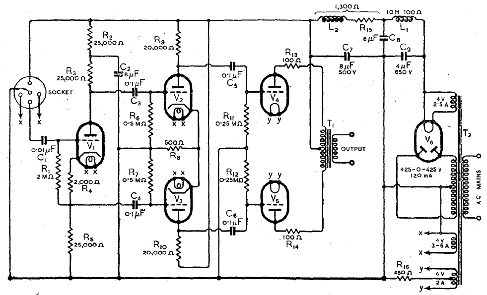
Apart from the appealing simplicity, I note the coupling caps needed at the input and between the stages. This is one more RC coupling than used in the Williamson, but there’s no global negative feedback to complicate the phase shifting. The placement of the concertina is also interesting here. By splitting phases before the drivers, rather than after such as seen in the Dynaco ST-35, Cocking is getting more gain per phase. Given the limited Mu in the tubes of the day, this was probably necessity.
This brings me back to the Hammond 1620As. I’m not going to be building with PX-4s or PX-25s, but the 6V6G that put out only 2W has had some spec bumps since Cocking’s day. We also have the benefit of transistors to assist us in squeezing out a few more watts and otherwise modernizing parts of the original design. Specifically, I’m eyeing the A2 grid lines provided on the 6V6 datasheets…

The 6V6GT triode-strapped is praised for its tone but lamented for its limited power. The Cocking Quality Amplifier looks like a great template that, with a few modern touches, will minimize the 6V6’s weaknesses and maximize its strengths. The push-pull loadline above looks like about 10W triode, a five-fold increase over the original application!

It certainly has an awesome name, and 10w triode strapped pp is great!
LikeLike