The ST70 is a beautiful and historic amplifier (and surprisingly compact if you see one in person). It’s also the best selling power amp of all time (at least so says Wikipedia). All things Dynaco inspire much talk here around the water cooler at the WTF Amps institute of higher learning about vacuum tube stuff. Here are some loosely organized tidbits and thoughts on amplification!
Generalized Topological Design Trends in Discrete Amplification
Forget for a moment that some amps are made with tubes while others are made with transistors. Deep down in their vacuum or silicon hearts they are really both just simple three-pin devices used to accomplish the same thing (gain). Forget all the audio-speak we abuse in our efforts to approximate the many facets of circuit performance. Forget the preconceptions we file away in our minds under “T” for tube or “S” for solid state. We aren’t thinking about tubes or transistors, right? Good.
To SE or PP (tee-hee)
Beyond all other aspects, the amplifier topology choice that impacts a design the most -in performance, efficiency, and cost- is whether the amplifier will be single-ended or differential. The difference can be boiled down to whether the amplification devices handle the entire signal through to the output (single-ended) or “split” the signal phases and re-combine them at the output (differential). Differential amplifiers are sometimes also referred to as push-pull. There is no such thing as balanced amplification, but that’s another discussion.
Single-ended amplifiers tend to be more inefficient in both a power consumption and economic sense. Because they are Class A by necessity, they dissipate more heat per watt of amplification. Single-ended amplifiers need a squeaky clean power supply to achieve a respectable noise floor because they do not benefit from the same kind of ripple rejection as differential amplifiers. They tend to produce more distortion, but the distortion that they produce usually has an even-order-dominated harmonic spectrum. Studies say even-order distortion harmonics are less offensive to most listeners.
In contrast, differential amplifiers produce less distortion when designed well, but what they do produce is dominated by odd-order harmonics, which are less pleasing to most listeners. Differential amplifiers are capable of far more efficiency than single-ended amplifiers because both output phases do not need to be “on” all the time. By nature, differential amplifiers reject power supply noise because they only amplify the difference between the phases and any power noise appears equally in both.
/r/outoftheloop
The distinction between single-ended and differential is the most fundamental taxonomy that can be applied to amps. The next most important design choice with regards to the circuit and its behavior is whether the amplifier will be open-loop or closed-loop. A closed-loop amplifier injects a portion of the output back into the circuit in order to correct non-linearities created by the act of amplifying with non-imaginary devices. This requires extra gain from the amplifier to be spent on suppressing these distortions. An open-loop amplifier is able to get by with less overall gain and enjoys more polite clipping behavior at the expense of generally higher THD. We are very deliberately avoiding the term ‘negative feedback’ here, by the way.
If you’re following along, you see that less-efficient single-ended amplifiers with less-objectionable distortion spectrum might naturally gravitate towards open loop circuits. Furthermore, you can imagine that more efficient differential amplifiers, with power to spare but a less pleasing distortion spectrum, are logical candidates for closed loop circuits. Your powers of comprehension do not fail to impress, dear reader. In practice a blend of single-ended and differential, open loop and closed loop, choices are made at the stage/component level in order to balance the relevant strengths and weaknesses, but the broader structure of amplifiers is usually one or the other.
WTF were we talking about again?
I’m going to tell you a secret now. Please do not react too loudly or cause a commotion. Come closer… Single-ended, differential, open loop, and closed loop has nothing to do with whether an amp uses tubes or transistors. Yes, that’s quite something isn’t it? While it’s true that historically certain devices and topologies are strongly associated one to another, this is a question of device availability coinciding with design trends and market demands, not choices dictated purely by the devices used.
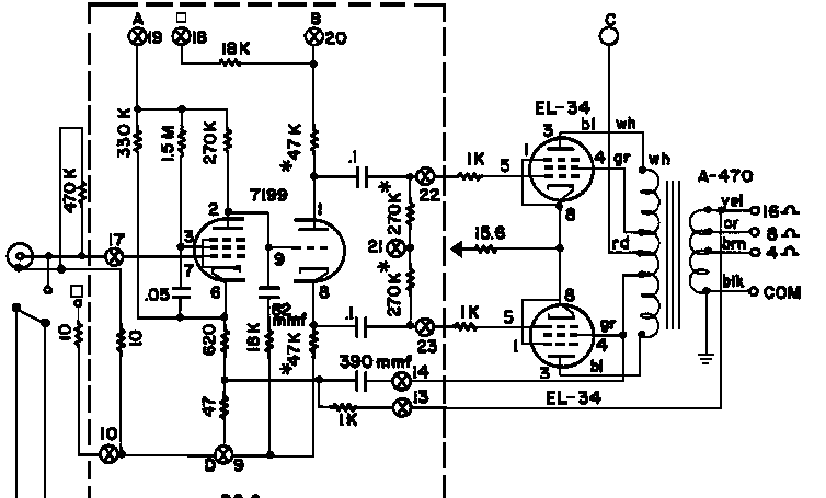
This brings us back to the topic of the Dynaco ST-70. This is a closed loop differential amplifier running in Class AB, much like the earlier Williamson or Leak tube amplifier designs. The overall topology is not much different from current Class AB transistor amplification because these solid state amps are simply a continuation of the same design trend (AB differential, closed loop). While today we associate tubes with single-ended open loop design and transistors with differential closed loop design – and all the baggage these topologies drag about – the reality is that performance has more to do with circuit choices than with the devices used.
The ST-70 was in some ways a pioneer. Though it was not the first of its kind, it was the standard bearer of the contemporary design values. Today we prize much of the ST70’s topological progeny in solid state Class AB (whether integrated on a chip or built with discrete components) but we also revere designers such as Nelson Pass who is charting his own course through both open loop single-ended transistor and Class A low feedback differential amplification. Amplifier design is not so much a timeline as it is a spectrum; the limits to what constitutes good amplification (subjective as that may be) are found not in the parts choices, but in the creativity of the designer.
TL;DR: Design, not device, makes the amp.
Here’s Dan Fraser’s write-up on the launch of the modern ST-70 series 3 (Dynaco was purchased by Radial Engineering in 2014)