Walking the line

When I got started with woodworking and amp building, cutting a straight line was the most intimidating part of just about any project. Not having the space or justification for a table saw, I tried more than one way of following a line with a jig saw and circular saw before I found something that works for me. Now I do not shy away from ripping boards to specific widths quickly and it only took some scrap and ingenuity.

What I found was a really simple circular saw jig made of a three or four inch wide 3/4″ board and some ten or twelve inch wide 1/8″ sheet. If you can find a board with a straight edge (preferably machined right from the lumber yard), you can cut a straight line. The jig is simply the 3/4″ board glued to the overly-wide thin sheet. You then zip your circular saw down the board with the shoe pressed against the straight edge to cut off the excess 1/8″ material. Viola. You now have a jig that will always cut just as straight as the board you used to build it.

saw jig

Here’s a picture of my jig (rebuilt this weekend because the old one was getting chewed up):

IMG_20170530_192959089
My board is a bit wider because I also use this with my router for insetting panels.

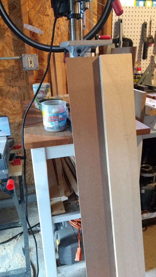
To use the jig, I mark the piece that will be ripped or cross cut in two places and then connect the dots with the now arrow-straight edge of the 1/8″ jig base. Clamp it down and then let the circular saw ride against the thick portion of the jig. Because the saw’s shoe doesn’t change width, it will always faithfully cut along the edge of the 1/8″ material, provided you are making sure it is following snug against the thicker board. Straight cuts don’t get easier than this and I’d wager that this is at least as fast as setting up a table saw for every cut.

As far as measuring, I’ve always got a combination square near at hand (great for marking holes in top plates, too). This makes setting a repeatable distance from an edge quick and easy.

IMG_20170530_192910549

If the thought of table saws and messy cuts prevents you from tackling your next amplifier or speaker project, hit the bargain bin at the lumber yard and whip up a simple jig.  This hobby doesn’t require expensive equipment if you get clever with the tools on hand.

New Project: La Luciérnaga (PSU)

This write-up will have two parts.  The first (the PSU) is posted and hopefully I’ll have the amp write-up done shortly.  This project is the most ambitious one I’ve written up for the site so please excuse the omission of some of the finer calculations and details.

Although the power supply is rather complicated, the amplifier will be pretty straightforward (pinky swear). The supply can be used with other amps and the amp can be used with other supplies, which is one of the reasons I decided to split it into two pages.

Click here to descend into the madness!

WTF Daydreams: Going Commercial

I was thinking on this topic yesterday (while in an economics lecture). One of the issues standing in the way of making a living from building tube circuits (aside from capital) is that there are few concrete competitive advantages that can be maintained in the long run. Tube circuits are no longer patented for the most part and so any company that sees sudden success signals to other potential participants that there’s money to be made. More participants shifts supply up, which shifts equilibrium price down. So the market price hovers around a modest break-even (priced around marginal cost, like commodities).

Perhaps that is too textbook (and also sophomoric; I’m not pursuing a degree in economics), but I think there’s some truth to the idea that tube circuits are largely unprotected from copycats and so the tendency for successful ideas to become commodities is at play. So, what other potential competitive advantages are there?

  • Schitt seems to have found a place in the market as a low-cost manufacturer of some tube products (mostly headphone). In a way, they have a first-mover advantage here as they got into large scale production of tube headphone amps as the market began growing (still is, I think). The first mover approach is to grow as fast as possible to raise the barriers to entry for potential competitors. The caveat is that constant growth and diversification is necessary to stave off these nagging competitors (who are motivated by the amount of success they perceive you have).
  • Historic companies like McIntosh Labs have brand equity that simply cannot be replicated overnight. Although there are plenty of alternatives in terms of comparable products, McIntosh has done a really good job with their image and catalog (IMO). Failure for them would probably be more self-inflicted than competition-based if it ever comes (selling out, not keeping up with costs, poor management, etc). Their advantage is that they can charge a premium price that would be unrealistic for start-up competitors.
  • The most interesting example I can think of is those companies that thrive on outrageous claims and marketing (ie snake oil audio). Their competitive advantage is imaginary, but to a large amount of people that doesn’t matter. If a competitive product appears, these companies can simply wave it away because it doesn’t have their personal flavor of delusion baked into it. Not that I condone this approach, but there’s no denying it’s out there. Look at an audio commodity like cables and how they are marketed.

So I think getting into tubes as a business requires a very real evaluation of what competitive advantage a company could bring to the market and how it can be protected in the long run (there are more strategies than those above, to be sure). In the short run, coming up with a good sounding circuit or a cool look will always sell a few amps, but success will always invite copycats and push price down.

On the bench: Zenith K731 (7M07)

This poor radio has seen better days and doesn’t quite live up to modern safety standards with regards to mains electricity.  But the look is great and there’s generous space inside for a small tube amp. Because the enclosure must be allowed to vent for the tube amp to dissipate heat, the speaker (which I also plan to modernize) will be a small challenge. This is a great candidate for a DIY tube radio restoration.

Probable features:

  • 3-5W single channel output
  • Bluetooth connectivity
  • Aux input (analog)
  • Volume control
  • EQ (either treble/bass knobs or loudness contour)
  • Safety!


DIY tube RIAA calculator sheet

All-In-One RIAA Calculator

Here’s a spreadsheet I built for calculating RIAA values in two stage tube phono preamps. When comparing results to other published designs using the same filter network, everything looks correct (within a few percent due to estimation of Rp). I used this sheet for El Matématico.

If you want to estimate values for something like a CCS loaded stage, you can set Rload on the appropriate stage to 1M or thereabouts. If you’re looking at using a cascode, mu follower, SRPP, etc 1st stage, you’ll need to make sure the Zout figure the sheet uses (cell I6)  reflects the Zout of the topology because it is used to calculate R1. Same thing goes for cell I3 (Miller capacitance of 2nd stage) if you use a gain stage after the filter that affects this (cascode, grounded grid, etc).

Go build a phono preamp!

“All-tube” MC phono preamp (continued)

Not long ago I wrote a short post about MC carts and the noise contribution of tubes when amplifying such tiny signals. I focused on step-up transformers as the solution to noiseless amplification, but there is another approach.  If you don’t like solid state, stop reading. Ok, now that you stopped reading and checked out the going prices for step-up transformers, you’re back. Good. Don’t worry, this approach uses the tubeyist solid-state device: the JFET.

A cascode is a compound amplifier in a totem pole arrangement. Here’s a great explanation by Valve Wizard Merlin. This allows you to achieve huge amounts of voltage amplification with fairly economic current usage and without coupling capacitors or multiple phase inversions. The driving force in this arrangement is the transconductance of the lower tube. The lower tube and upper tube do not need to be the same, nor do they even need to be the same type of device.

JFETs (junction gate field effect transistors) are voltage controlled devices, just like tubes. In fact, they bias in a very similar way: Rsource in the above raises the n-type JFET’s source voltage above the gate, similar to the way a cathode resistor in a grounded cathode amplifier raises the cathode above the grid. On the other hand, even the lowliest JFETs have a higher transconductance (gm) than the mightiest small-signal tubes. Icing on the cake is that JFETs, properly chosen and cared for, are lower noise devices. As such, they make a great lower device in a hybrid cascode.

The overall gain of a cascode simplifies to approximately:

gm(lower) * Rload

This equation is a simplified expression of the total gain of both devices:

[gm * (Rp + Rload) / (Mu + 1)] * [(Mu +1) * Rload / (Rp + Rload)]

AKA [JFET gm * load divided down at tube’s cathode] * [grounded grid gain of tube]

Rp and Mu are characteristics of the tube upper device. The choice of upper device affects how much of the voltage gain is performed by the JFET by affecting the load it sees. A high Mu and low Rp upper tube (i.e. high transconductance) presents a lower load as divided down at its cathode, thus less voltage amplification by the JFET (and more voltage amplification made up by the tube due to the higher Mu). A low transconductance upper tube does the opposite. But regardless of the tube (assuming an appropriately sized Rload), the overall gain remains the same: ultimately the transconductance of the JFET multiplied by the load on the upper tube.

So where’s this headed? Obviously there’s a full design coming to try out this idea, but the takeaway is that a hybrid cascode is potentially a great way to step up the tiny signals from a moving coil cartridge with very low noise and hand the now-larger signal off to a tube amplification stage without multiple supply voltages, coupling caps, or an expensive step up transformer.

The catch? Cascodes have poor power supply noise rejection and a fairly high output impedance. But there are ways to minimize these factors, too.

Further recommended reading: 1, 2, 3, 4

Coming soon to a workbench near you…

In a world where near-field and headphone listening has become an unstoppable force. Where every DIY builder is bored to death of rational and safe two-stage, single-ended triode designs. Where power supplies have become an afterthought and parts values are just plugged and chugged. Prepare your butt for a new madness. Prepare it for La Luciérnaga…

the-big-sheet

Note db scale for the predicted frequency response graph: +/- 1 dB from 40-20khz. If that’s not good enough, I’ll show you how to make it even better. There’s mucho tube math coming your way, amigo.

Here’s the worksheet I used to create the above:

two-stage-set

Letters to WTF: All-tube MC phono preamp?

Q:
 ­
Why not build an all-tube MC phono preamp?
A:
 ­
I haven’t built an all-tube MC phono preamp.  I build MM stages with the assumption that MC users will use step up transformers. Generally, its much easier to keep the whole thing quiet that way. This is a simplified explanation, but I hope it gets the general idea (SNR) across:
 ­
Tubes impart noise in a few ways but they’re all usually tiny.  MC carts need around 60-70db of gain to bring them up close to line level.  This is multiplying the MC signal from the cart by 1000-3000x before it gets to your amp. In contrast, a MM cart usually needs 40-50db, which is an amplification of 100-300x.**
 ­
The more tubes used, the more very tiny sources of noise get introduced.  Although the noises are tiny, they are amplified by the preamp, just like the signal. So the more gain required to get the signal to a desired listening level, the closer the tiny noises get to being audible as well.  Several stages of tubes for a very large amount of gain can lead to unwanted noise for this reason (guitar amps and phono preamps are both good examples of this).
 ­
The step up transformer cannot practically do more than about 20db-25db of gain without having some undesired consequences, but they don’t have ‘moving parts’ and are very good at rejecting noise/hum.  The 25db of gain from a transformer is enough to lower the tube gain needed from 3000x (70db) to 175x (45db), meaning any noise from the tubes is amplified much less. It’s kind of like giving the tube part of the preamp a head start in the race against noise.
 ­
So that’s why I haven’t built a MC phono preamplifier. If I were to build one, I’d most likely add step up transformers to a MM preamp like the El Matematico or similar.  To me, this is the most practical approach with the highest likelihood of success.
 ­
 ­
**At the risk of muddying the waters, phono preamps actually need about 20db more than the numbers mentioned here but this is then attenuated by the RIAA correction filter to result in ~40db or ~60db net gain, MM and MC respectively.