Another update from the tube bunker

I’ve made more progress on the workshop room where my little tube hobby shop will soon live. Since the last post, I’ve ripped out a section of built-in shelving, framed the rear wall, had electrical installed, and covered said framed wall with 1/2″ plywood.

This plywood wall will eventually house a workbench for electronics and assembly as well as shelving (potentially a french-cleat type solution). The rest of the room is also taking shape with the addition of a small cart for my drill press and a section of peg board for hanging hand tools.

I still have plenty to do, but with a non-zero chance of a coronavirus quarantine, it’s very possible I’ll be spending more time in the tube bunker than expected. Next order of business is to build some drawers for the press stand and the workbench itself. When that is done, I’ll feel much more settled in the new space.

Letters to WTF: how do you test a build?

Q: Hi, I’m working on a schematic from your website. How do you usually test your circuit, as you go, or once everything is wired?

This is a great question. The short answer is that it depends. On a simple build with just one or two stages and passive loads and power supply filters, I will probably finish all my wiring and then power up and test. On a complex build with things like active loads, multiple bias voltages, or regulated power supplies, I will test as I build. In both cases, my general testing process is fairly similar.

  1. Connect the project to a variac or light bulb current limiter (if available).
  2. With only rectifiers installed (no other tubes), power on and measure B+ voltages. These will be higher than the voltage levels with the rest of the tubes installed, but should be in the ballpark.
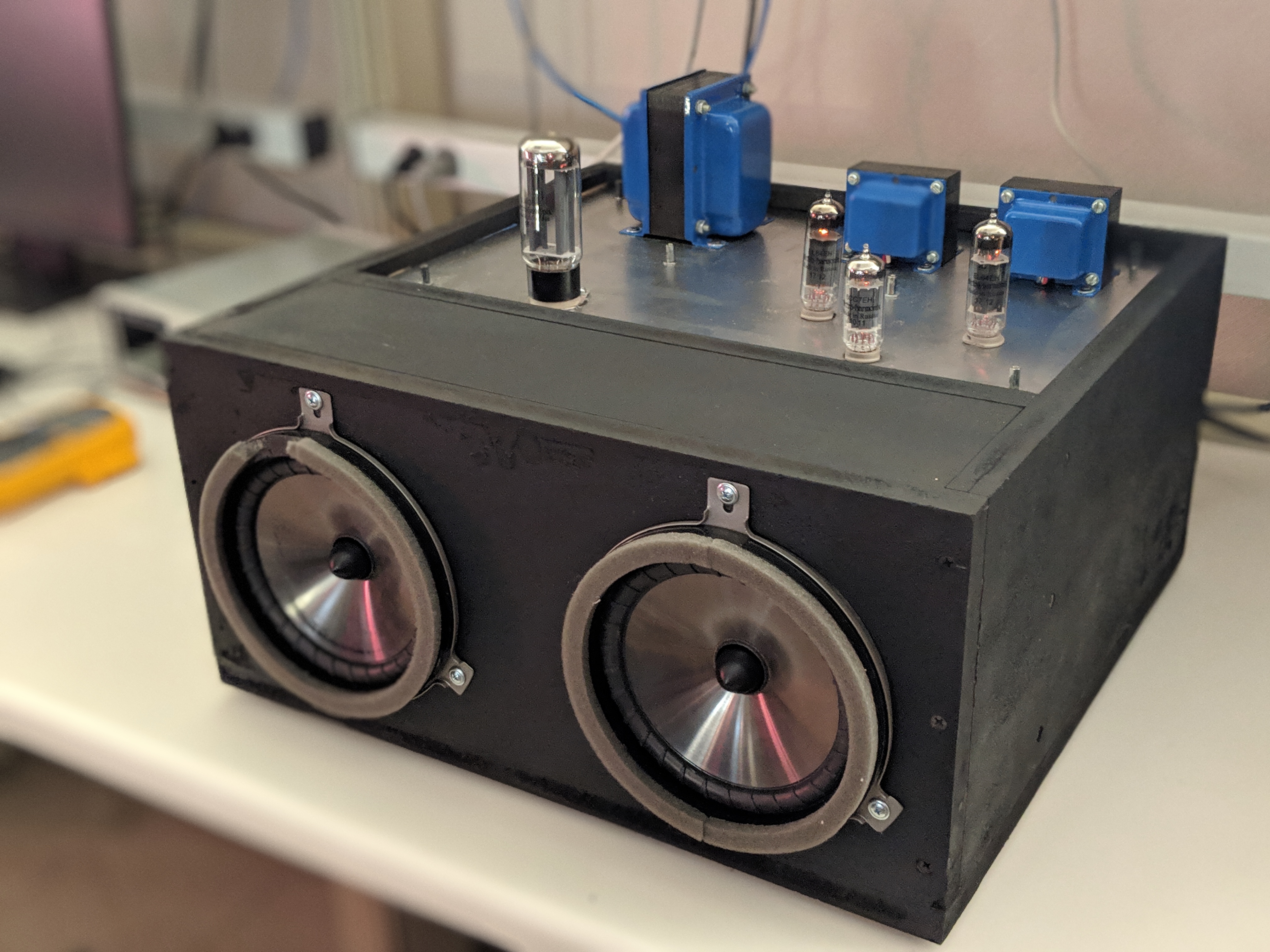
    • 2a If using any circuits on PCBs, I will test before installing in a chassis if my external power supply and loads allow it.
  3. Install preamp tubes and measure bias points to be sure they’re in the right ballpark. If fixed or directly biased output stages, measure bias levels. The B+ is still a little high at this point.
  4. Install output tubes and dummy loads, and measure current draw and bias point. The B+ should now be at roughly the calculated level. Adjust bias if needed.
  5. Connect to cheap speakers and debug hum/noise. Let the project run for extended periods of time and generally abuse it a bit.
  6. Hook-up to the main system and crank it!

At each step, any trim pot adjustment appropriate to the stage would be adjusted as needed. Typically I will have one digital multi-meter (DMM) on the B+ at all times and additional meters to measure individual tube bias. I use alligator clips and connect/disconnect meters with projects powered down. Don’t poke around live amps if you can help it!

New batch of boards!

Another batch of boards just arrived for some of my upcoming projects and experiments. These include:

  • MOSFET driver for A2 output stages
  • FW rectifier+voltage doubler combo on a compact board
  • MOSFET cap multiplier and CCS for DHT filaments
  • Shunt cascode boards v2 (slight layout changes to previous version)
  • MOSFET “gyrator” anode load
  • Low voltage bipolar supply (LM317 and LM337) for opamps

Some of these will be used for upcoming phono and line-stage builds while others are daydreams that I’ll get around to eventually 🙂

Reminder: extra PCBs are available for free or for purchase to my Patreon supporters

New page: gyrators

Ok, so what we often call a gyrator is not technically a gyrator. This page is named after the circuit popularly referred to as a gyrator, not an actual gyrator.

I’m developing a little PCB for a simple gyrator circuit to be used in an upcoming integrated preamp project (2nd stage of phono circuit: needs gain and low enough output impedance to drive a volume pot). The thing that’s most intriguing to me at this point is how a gyrator lets you set an anode voltage rather than anode current (but still maintains a high impedance for AC). On paper, this looks more flexible in rolling compatible pinout tubes than setting a current. And what the heck, it’s a new circuit to try!

See the new page here!

A Mighty Cacahuate caught in the wild

Student “D” sent me some pictures of his Mighty Cacahuate project with a twist and it’s too unique not to share. D developed a PCB for his build and mounted all the amplifier parts to a top plate as would usually be done. Instead of a boring wooden box, D dropped this into a boombox enclosure for all-in-one listening. I love to see the creative use of a basic schematic I posted here on my little website.

We initially troubleshooted some wiring over email, mostly due to my omission of the details of heater wiring and pin numbers on the original schematic. Once sorted though, D says the amp started playing and sounding great without a hitch.

It was an amazing feeling the first time they powered on.

-D

Careful there, D, that feeling is habit forming!

Update on the mono-blocks: left channel is done and right channel is coming together quickly. Write-up for the project is also underway. Looking forward to playing in stereo!

EL34 tester tubes, also considering springing for KT88s on this project
Night shot. Red glow through the vents is LEDs used as voltage references in CCSs inside.