Line stage + phono build underway

In a recent post I set a goal for myself of creating a couple of preamp designs that included both line stage and phono preamp circuits. The first of these builds is now underway! Because of the number of input and output jacks as well as switching and volume controls, I’m using a different style chassis than the all-wood apron approach in most of my builds. The face plate and rear of this enclosure are aluminum with wood (walnut here) used as accent panels on the sides.

I’m emphasizing the sleeker look by mounting all of the transformers inside the chassis. The power supply is mounted to a section of aluminum c channel that also serves to section off all of the AC power from the rest of the chassis (which will carry sensitive signal circuits). So far so good. We’ll know if the approach to shielding and layout is effective once it’s powered up and playing. Placement for the signal portion will be finalized after I’ve mounted the front panel controls into the 3/8″ aluminum flat. I expect that to be a bit of an adventure…

The generic circuit for this build is below (final values will be published once it’s tested). Tracing the path of a phono signal: the resistor loaded input stage feeds the RIAA correction filter which feeds a gyrator loaded output stage. I’m using a gyrator as a flexible load to allow for tube swapping as well as a low output impedance device to effectively drive the follow control that follows after the selector switch. The volume control feeds a transformer loaded 6H30.

The Edcor GXSE 15k:600 output transformers are an experiment here. Reading through others’ experiences and measurements, I think the 6H30 is going to be a suitable driver with good bandwidth if it’s given enough current. I expect to do some experimenting with loading the secondary.

All in all, this will be all 9-pin current production tubes and parts. If the execution works out as well in real life as it does on paper, it will be a great, relatively-affordable preamp build.

Combining Line Level and Phono

I love boxes with tubes sticking out as much as the next DIYer. Generally, the more boxes, the better in my mind. In practical domestic life however, lots of specialized chassis (beautiful as they may be) don’t always translate well to limited space or the aesthetic considerations of cohabitants (AKA: WAF).

The phono and line-level functions are a good place we can look to consolidate our pretty enclosure collection. The voltage levels are manageable, the current requirements are usually low, and the tubes used are not especially large (in most cases). The question then is how best should we integrate something like a phono preamp and a line level preamp.

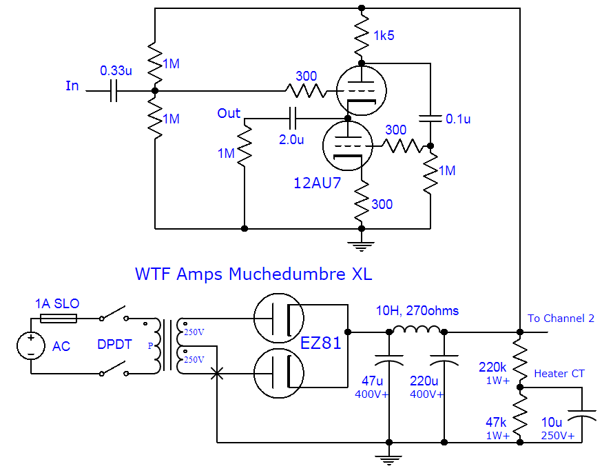
The schematic above gives an idea of the approach I intend to take for this kind of phono+line level project. A phono signal travels through an RIAA section sandwiched by two gain stages. This is attached to one input of a three way switch; the other two inputs at the switch can be used with a CD player, streamer, or other source of your choice. The output of the switch feeds a volume control, which in turn feeds a transformer-loaded single ended output stage.

Using a transformer on the output allows us to set a nice low gain for the line level section. Although a CD player probably won’t need it, some vinyl recordings and cartridges benefit from a small boost (e.g. 2x voltage gain, 6db). The transformer also allows us to step down our output impedance, much like the cathode follower in the Muchedumbre project. Of course, line level output transformers that can be used in a series feed configuration are not usually cheap.

I have a pair of Lundahl 1660 AM transformers to be used in this project. These run around $500 a pair (via kandkaudio.com). They are a well-known transformer for exactly this application. I have also purchased a pair of Edcor GXSE 15k:600 transformers ($40 a pair) as a budget-minded comparison. The transformer ratios are similar (4.5 or 5 to one) and both can be used in series-feed applications. While the Lundahl datasheet is very detailed, you may have some trouble getting inductance and DCR specifications from Edcor.

This is a tale of two preamps. I intend to design and build two all-in-one preamps with the same overall topology, but different tubes and parts. One preamp will be built using NOS tubes and high-end parts, while the other preamp will be built using current-production tubes and every-man components. I’m very excited to hear how the two projects compare and to be able to publish more than one option for people looking for an all-in-one preamp project.

More to come on this topic as I work-out the circuits and parts choices!

Muchedumbre XL

The regular Muchedumbre is an ultra-simple buffer with few parts and straightforward operation. It’s a great beginners circuit for high voltage tube applications.

If you’d like something with just a little more nerd sprinkled on top (and an extra 12AU7), try the following. This XL version uses a White Cathode Follower buffer for about half the output impedance of the vanilla version. It requires a few extra resistors and caps and the heater reference voltage is tweaked just slightly so I can sleep better.

For ideally symmetrical drive ability, the series resistor in the anode of the upper 12AU7 should be calculated as:

Rseries = (Rp + 2 * Rload) / Mu

Plugging in values for a 12AU7 and a (worst case) 10k input impedance gives you about 1k5 (rounded so that it’s an easy to find value). You can optimize this for the input impedance on your amp using a plate resistance number of about 7k and Mu of 20. Just keep in mind that the resistor is in series with the tubes and so it drops B+ voltage based on the current at the bias point.
I am assuming a low input impedance on the amp and so the calculated value is also on the low side, but this preserves operating voltage and overhead. The actual drive current required in a typical preamp output stage is very small, so even a loosely optimized WCF is plenty capable. When in doubt, use smaller values for the series resistor for line level. If we were trying to drive something needing lots of current swing like a bunch of parallel output tubes or headphones, we’d be pickier about Rseries.

Muchedumbre XL

If we break down the circuit into a cathode follower (upper triode) and a grounded cathode amplifier (lower triode), we can see that this creates a nifty push pull circuit. The cathode follower is non-inverting, so it’s pulling the output in the same direction as the input signal. The lower triode is a grounded cathode amplifier and so it inverts the input that it sees. But the input that it sees is from the anode of the upper triode, which is already inverted. You invert the inverted and you get non-inverted (same ‘direction’ as the upper triode). Tada!  Push (lower) pull (upper).