Lookee here, itsa project!

Not that I’ve had any shortage of projects lately, but they’ve all been workshop or home related. Now that the workshop is “done,” I’ve finally found a little time to return to tubes.

Many blogs ago, I posted about using switch mode power supplies (SMPS) in multiples to provide B+ for more typical tube operating points. That’s ‘typical’ as in 300V+, not the 48V of El Estudiante or other similar low voltage designs. I don’t see anything wrong with low voltage if it sounds good and meets a design goal, but it does hinder the tube and topology options.

A few posts later, and still stuck on the stacked SMPS idea, I proposed a tube that might do well as a linestage with only 100-150V B+. The 6AF4 is a 7-pin triode with a modest Mu and low enough plate resistance to drive amps with a 20kohm+ input impedance without the assistance of transformers or followers. In short, it could make a really simple preamp with a really simple power supply for a really modest cost.

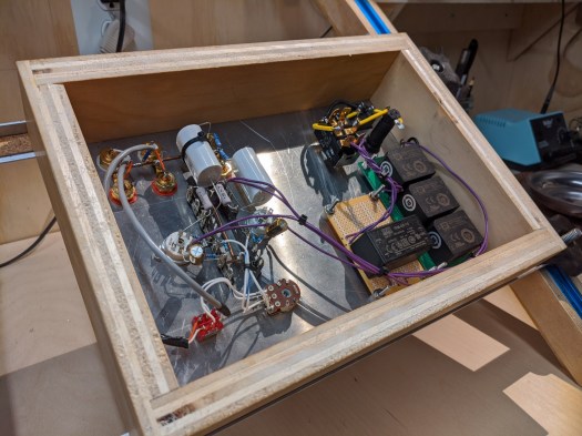
And that’s what I did:

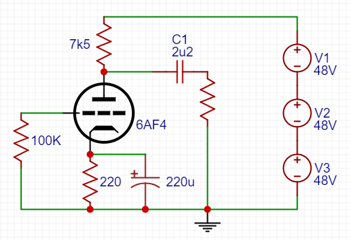
The power supplies V1-V3 are XP Power VCE05 48V modules on a small PCB with some small capacitance filtering on the output (10uF). The heater supply for the tubes (one per channel) is a small 12V Meanwell IRM-05-12. Total cost as of this post is about $45. Current cost on a Hammond 269BX (300V CT) is $55 and you’d still need to rectify and filter to make a workable supply.

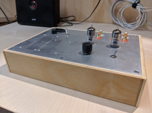
With the low parts count, sleeper tube, and inexpensive (and simple) power supply, this is a great cheap and cheerful project. It also sounds quite nice in use so far. I’ll update with a more complete write up including operating points, construction tips, and listening impressions soon!

Muchedumbre XL PSU details

These two buffers are very similar. In fact, the XL came about as a simple mutation of the regular version when the cost/size of an extra tube was not an issue and there was the possibility of driving a lower impedance load (long cables, solid state amps, etc). In theory, the power supply requirements are identical down to the B+ current draw. “In theory.” Although if you study the schematics carefully and read the write ups, you’ll see that my steel-trap mind is missing a spring or two.

The original Muchedumbre called for a Triad C-3X (500 ohm DCR). On the schematic for the XL, I seem to have spec’d the Traid C-7X (270 ohm DCR). The inductance rating for these two chokes is identical, but the C-7X has about half the DCR. Is that going to be a problem?  In short: no. I love tubes; they make up for all my shortcomings.

Current draw between the two configurations (XL vs vanilla) is the same on paper, despite the extra triodes in the XL (the added triodes are in series, so the same current flows through both). If using the same choke, the B+ should end up the same. With the modest current in the pre, however, you have plenty of leeway in DCR before you have to worry about big B+ changes.
ΔVdchoke = (500 ohms – 270 ohms) * (10mA x 2) = 4.6V
No problemo.
Say you have a big old Hammond 193M at 10H and 63 ohms DCR. You could very safely use that, too. The lower DCR gives you a little more room in the B+ to increase the series/sense resistor if you’re amps’s input impedance suggests it. You gain some B+ in the choke DCR and drop it back down across the sense resistor. Current across the DCR is twice that of each channel, so assuming 10mA bias per channel:
ΔVdchoke = (500 ohm spec – 63 ohm part) * (10mA bias x 2 channels) = +8.75V
ΔVdsense = (1k5 ohm spec – 3k ohm part) * 10mA bias = -15V
Net result is a 6.25V deviation from the ‘on paper’ spec’d parts. That’s less than 5% of the B+, so better than parts tolerance in a lot of cases (e.g. low frequency chokes). The x-axis divisions on most tube datasheets are 20-25V, so they’re only so precise. Generally, 10% changes in B+ based on available part specs is probably about where I would return to my load lines to recalculate. In practice, I sometimes build anyways and then measure actual B+ before worrying about anything.

Solder and wire beats paper and pen.


(power) supply chain

Postponement is a powerful supply chain concept employed to minimize inventory/capital for a business by delaying configuration of a specialized product until as close as possible to delivery to the end-user. For great examples, see Dell’s made-to-order computer business or Edcor’s made to order transformers.

In vacuum tube land, the transformer is a critical component. Tubes come in all shapes and sizes, requiring a variety of voltages for optimal operation. This has lead to many different power transformers and filter configurations for various circuits. We even have transformer companies whose entire business strategy is founded on servicing the myriad of transformer configurations and custom options.

What if we could find one power transformer that could be used with any circuit? What would it look like? Well, if I were to build one it would probably look something like this:

2018-02-19_14-41-28

Looks pretty simple to be universal, doesn’t it. But what’s up with the 50V winding? It’s not a heater tap but it could be used for bias, I suppose. The use I have in mind is something like this:

In conjunction with the 300V winding, the 50V winding will allow you to create 250V and/or 350V outputs (all voltages AC of course). Using the extra winding and some filter math, you could easily tune in any target B+ from low max voltage tubes like 6V6/EL84 to higher max voltage tubes like EL34 or KT88. Careful attention would need to be paid to phase labeling and any power supply would use a bridge rectifier, but those are pretty small prices to pay for more flexible parts.

A transformer like this with a 250mA current rating might be the only transformer a builder would ever need for a variety of projects. Fewer parts means less money tied up in iron for users and fewer SKUs means more economies of scale for transformer manufacturers. That’s the beauty of postponement.

Bench update:

  • Aikido Headphone amp is underway
  • Push-push octal monoblocks are in design phase
  • Working on write-up for latest peanut watt SET “El Cacahuate”

Simple high current VR tube regulator

VR and transistor regulator

If you’ve looked through many of the designs on this website, you’ll see I have a love of glowing things. A current project of mine requires a ~150V supply and my mind immediately went to the beautiful purple glow and sultry curves of the 0D3 VR tube.

close up 0d3

The problem was that I wanted around 40mA from the supply. In the usual VR tube shunt regulator configuration, we’d size the ballast resistor based on the load current and the current we want through the VR:

vr resistor calc.png

With a large load current, the ballast resistor (Rb) will be small. But at start up with a tube amp/preamp, the load current will be zero until the heaters are warm. This will force the VR to pass the entire load current (in addition to its own quiescent current) until the rest of the circuit is warmed up. VR tubes are generally specified for only 5-40mA. Too much current at start up will stress the VR, leading to a shorter lifespan and potentially arcing.

Transistors to the rescue. The simple schematic above uses a VR tube as a voltage reference on the base/gate of a BJT/MOSFET. The emitter/source provides a very low output impedance to the load.  The output voltage is the VR tube reference voltage (150V for 0D3) less the Vbe of the transistor (approximately 0.7V for BJTs and 4-5V for MOSFETs). The current limit in this configuration is limited by the pass transistor and heatsinking, rather than the VR tube.

I’ll be building and testing this supply in the near future with an 0D3, but I don’t see any reason it shouldn’t work with 0A3, 0B3, 0C3, and/or series combinations of these voltage references. Just be wary of the transistor max voltage.

Shunt regulator proposal

Although I love me VR tubes something fierce, they aren’t in current production and I’d like a simple (or well as simple as possible, I guess) shunt regulator alternative for things like phono preamps or line stages (20mA of load current or thereabouts).

This shunt regulator uses an EL84 for the heavy shunt lifting and a 12AX7 differential amplifier (using non-inverting output) to amplify any ripple on the output (which the EL84 ‘cancels’ across Rs). Quick calculations look like about 100V of headroom would be nice to have so rectified 250Vac with the shunt should be good for about 250Vdc regulated output.

Update: Putting the differential amplifier before the shunt will unload it a bit and provide more B+ headroom for higher gain.

dc-shunt-reg-v3

New Page: Shunt Regulators

shunt-reg

I’ve been doing some reading on tubes in shunt regulator power supplies lately (lots of great articles on TubeCAD including this one).  I’m planning to incorporate one in an upcoming build.  In operation, this isn’t too different from the VR regulator power supply in my Matemático Phono Preamp, but a shunt regulator with a triode would have an adjustable output and might afford even better ripple rejection.

My recent series regulator project is another example of power supply regulation.

Click here to see the new page on shunt regulators.