

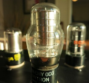
If you’ve looked through many of the designs on this website, you’ll see I have a love of glowing things. A current project of mine requires a ~150V supply and my mind immediately went to the beautiful purple glow and sultry curves of the 0D3 VR tube.
The problem was that I wanted around 40mA from the supply. In the usual VR tube shunt regulator configuration, we’d size the ballast resistor based on the load current and the current we want through the VR:
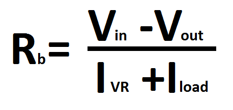
With a large load current, the ballast resistor (Rb) will be small. But at start up with a tube amp/preamp, the load current will be zero until the heaters are warm. This will force the VR to pass the entire load current (in addition to its own quiescent current) until the rest of the circuit is warmed up. VR tubes are generally specified for only 5-40mA. Too much current at start up will stress the VR, leading to a shorter lifespan and potentially arcing.
Transistors to the rescue. The simple schematic above uses a VR tube as a voltage reference on the base/gate of a BJT/MOSFET. The emitter/source provides a very low output impedance to the load. The output voltage is the VR tube reference voltage (150V for 0D3) less the Vbe of the transistor (approximately 0.7V for BJTs and 4-5V for MOSFETs). The current limit in this configuration is limited by the pass transistor and heatsinking, rather than the VR tube.
I’ll be building and testing this supply in the near future with an 0D3, but I don’t see any reason it shouldn’t work with 0A3, 0B3, 0C3, and/or series combinations of these voltage references. Just be wary of the transistor max voltage.
