A Muchedumbre XL in the wild

HM in the Netherlands shared a beautiful Muchedumbre XL build with me recently. He adapted his build to use a pair of Telefunken ECC83s (jealous). My notes on tweaks from our emails:

“In the Muchedumbre XL, adapting for different tubes is not so difficult (compared to resistor loads). A tweak to optimize for a 12AX7 in this circuit would be to lower the Rseries value a bit (1k5 in the original schematic). For a 12AX7, a value closer to 1k is optimal but this also depends on the amplifier you’re driving. I would not say this value is too critical unless you have a very low input impedance on your amplifier.
The other value to tweak is the cathode resistor (300 in the schematic for 12AU7). A 12AX7 may be happier with a higher value here. Something around 1k-1k5 gives you more signal swing before grid current which is generally a good thing.”

He also includes a 45 second bypass relay based on the NE555 to save his powered speakers on power on and off.

Beautiful build, HM!

Additional pictures of wiring and testing:

Lookee here, itsa project!

Not that I’ve had any shortage of projects lately, but they’ve all been workshop or home related. Now that the workshop is “done,” I’ve finally found a little time to return to tubes.

Many blogs ago, I posted about using switch mode power supplies (SMPS) in multiples to provide B+ for more typical tube operating points. That’s ‘typical’ as in 300V+, not the 48V of El Estudiante or other similar low voltage designs. I don’t see anything wrong with low voltage if it sounds good and meets a design goal, but it does hinder the tube and topology options.

A few posts later, and still stuck on the stacked SMPS idea, I proposed a tube that might do well as a linestage with only 100-150V B+. The 6AF4 is a 7-pin triode with a modest Mu and low enough plate resistance to drive amps with a 20kohm+ input impedance without the assistance of transformers or followers. In short, it could make a really simple preamp with a really simple power supply for a really modest cost.

And that’s what I did:

The power supplies V1-V3 are XP Power VCE05 48V modules on a small PCB with some small capacitance filtering on the output (10uF). The heater supply for the tubes (one per channel) is a small 12V Meanwell IRM-05-12. Total cost as of this post is about $45. Current cost on a Hammond 269BX (300V CT) is $55 and you’d still need to rectify and filter to make a workable supply.

With the low parts count, sleeper tube, and inexpensive (and simple) power supply, this is a great cheap and cheerful project. It also sounds quite nice in use so far. I’ll update with a more complete write up including operating points, construction tips, and listening impressions soon!

No workshop, no time, what do?

Having recently moved and had a second kid, tubes should be the last thing on my mind, right? Maybe. Then again,personal hobbies should always have a place in day-to-day life, and especially when that life gets a little chaotic. Such hobbies are about exploration and continuously challenging oneself. And yes, sometimes a little bit of dorky obsession.

Hence, with all my tools in boxes and precious little spare time, I have a great opportunity to revisit quick, cheap, and cheerful tube design (at least this is what I tell myself).

Last spring I posted about a sleeper tube that looked to me like it had potential in a simple linestage. The single triode has modest B+ requirements, low Mu, and respectable transconductance, exactly what we might look for in a bare-bones capacitor coupled preamp. To boot, the tube is called 6AF4. AF. How could I resist?

Here are the plate curves, highlighted where it looks pretty good to me:

It looks like we could work with as low as a 100Vdc supply here, but plate resistance appears lower and more consistent if we have 150Vdc on tap. With 150V B+, a 7.5k loadline passes right through the middle of my target zone of operation, intersecting the y axis at 150V/7500 ohms = 20mA. A 220 ohm cathode resistor looks like a good place to start and should allow a dozen or so milliamps through the triode. The result, fleshed out, looks something like this:

Back in my original post on the topic, I mused about 48V switching supplies wired in series to generate a B+. That’s a monkey I still haven’t gotten off my back, so I drew up a little PCB based on the XP Power VCE05 module. This is a $12 encapsulated AC/DC converter that puts out 100mA+ at 48V. Three in series gives ~150V in a very compact footprint and at a cost comparable to a small Hammond EI transformer.

Although a pair of 6AF4s will only need 25mA or so, a pair of these boards would (hypothetically) be capable of powering a small power amplifier (300V @ 100mA). It’s worthy of some exploration.

A Muchedumbre in the wild!

As I mentioned in a couple recent posts, my workshop is in boxes while moving. Good news is that those boxes are finally in the new space and just need the shelving built to unload them.

In the meantime, here are some pics of a Muchedumbre build by someone else! As you can see, PB has a very tidy build on a compact footprint. He reported no issues with the simple circuit in our email exchange and says it sounds fantastic! I love the way he’s matched it with the speakers and other DIY components. Very attractive.

I hope to be back posting about my own adventures again soon. First step is to measure the new space and start laying out the shelving and workbenches for the shop…

A cheap sleeper tube thought experiment

One day I was combing through tube characteristics using the parametric search function in the Tube Data Sheet Locator desktop app and I came across an interesting 7-pin triode. As luck would have it, I happened across a couple at a swap meet about a week later when the tube type was still fresh in my mind. I bought them, thinking they might be interesting to experiment with.

The 6AF4 is a 7-pin indirectly heated triode. I found the 6AF4 interesting because of its fairly low amplification factor (Mu of 15), decent transconductance, and high perveance. These characteristics suggest that a really simple and fairly low voltage preamp may be within reach. Check out the datasheet here (link to PDF).


I’d power this with a pair of 48V SMPS in series and wire the two 6AF4 heaters in series to be powered by a 12V SMPS. This would bring PSU costs and size down significantly. Voltage gain here would be about 10 and output impedance should be a little under 2k ohms.

Because resistor loading will still provide a lot of gain, even with a low Mu of 15, this version uses a matching transformer to step down gain and output impedance. Voltage gain here would be 2 or 3 and output impedance should be a couple hundred ohms. Edcor makes affordable candidates for output transformers in this application (WSM series). I’d also look for second hand matchers in the 2:1 to 5:1 range.

As far as a loadline and bias point, the blue blob area looks pretty good to me. Note how low the supply voltages are here. These low voltages make parts both cheaper and smaller. While I like the lower output impedance and fanciness of parafeed, the resistor load would probably sound a little tubier. It would also be simpler, cheaper, and more compact.

Whelp, I seem to have talked myself into it…

Workshop toys and a different style chassis

I recently spent some time in the garage workshop on a non-tube project I’ve been meaning to do for quite some time. Up to now, my chassis have all been a mitered box with a lip to inset the top and bottom plates. I cut the lip with a straight edge and a hand-held router. This works fine and produces good results, but setting it up for the cuts was a chore. The better solution for this kind of rabbet with a fixed width/depth is a router table, so that’s what I built!

My new table includes a white-board top, inset aluminum plate for the router, and t-track to adjust the fence distance. The fence has adjustable stops so I can get close to zero clearance and add shims to plane edges or remove small amounts of width from boards. This will all make cutting the same chassis I’ve been doing much quicker. It also opens up some new chassis possibilities:

Here’s a different style chassis that I’ll use in the next preamp build. The sides are still wood and include a lip to inset the top and bottom, but the front plate is 1/4″ aluminum and the back is an aluminum c channel. This will make drilling for jacks and controls much easier than using a 3/4″ wood panel. Making the same enclosure with decent precision would have been much more difficult without the new router table.

More updates to come as I begin this preamp project!

Combining Line Level and Phono

I love boxes with tubes sticking out as much as the next DIYer. Generally, the more boxes, the better in my mind. In practical domestic life however, lots of specialized chassis (beautiful as they may be) don’t always translate well to limited space or the aesthetic considerations of cohabitants (AKA: WAF).

The phono and line-level functions are a good place we can look to consolidate our pretty enclosure collection. The voltage levels are manageable, the current requirements are usually low, and the tubes used are not especially large (in most cases). The question then is how best should we integrate something like a phono preamp and a line level preamp.

The schematic above gives an idea of the approach I intend to take for this kind of phono+line level project. A phono signal travels through an RIAA section sandwiched by two gain stages. This is attached to one input of a three way switch; the other two inputs at the switch can be used with a CD player, streamer, or other source of your choice. The output of the switch feeds a volume control, which in turn feeds a transformer-loaded single ended output stage.

Using a transformer on the output allows us to set a nice low gain for the line level section. Although a CD player probably won’t need it, some vinyl recordings and cartridges benefit from a small boost (e.g. 2x voltage gain, 6db). The transformer also allows us to step down our output impedance, much like the cathode follower in the Muchedumbre project. Of course, line level output transformers that can be used in a series feed configuration are not usually cheap.

I have a pair of Lundahl 1660 AM transformers to be used in this project. These run around $500 a pair (via kandkaudio.com). They are a well-known transformer for exactly this application. I have also purchased a pair of Edcor GXSE 15k:600 transformers ($40 a pair) as a budget-minded comparison. The transformer ratios are similar (4.5 or 5 to one) and both can be used in series-feed applications. While the Lundahl datasheet is very detailed, you may have some trouble getting inductance and DCR specifications from Edcor.

This is a tale of two preamps. I intend to design and build two all-in-one preamps with the same overall topology, but different tubes and parts. One preamp will be built using NOS tubes and high-end parts, while the other preamp will be built using current-production tubes and every-man components. I’m very excited to hear how the two projects compare and to be able to publish more than one option for people looking for an all-in-one preamp project.

More to come on this topic as I work-out the circuits and parts choices!

Letters to WTF: Holiday Gifts for the Tube DIYer?

Q: A simple question – is it possible to purchase a kit from you? If not, are there decent kits you would recommend for a first-time tube build? My husband has built a couple of solid state preamps and power amps and is intrigued by tube ware.

A: Your husband is a lucky guy to have someone encouraging his hobby!

I don’t sell any kits for my builds at this point (though I do send out prototype PCB boards to my Patreon subscribers on occasion). I am happy to provide some recommendations for beginner-friendly tube projects and/or gift ideas, though. Some of these are PCB boards that require you to select parts (or leave your husband to do so afterwards). Many builders enjoy the process of picking out and sourcing parts, so this isn’t necessarily a bad thing  and you might include a ‘parts budget’ as part of the gift in that case. 

Tubecad.com makes some of the best documented and flexible board kits you can find for tube hobbyists.  In particular, the Aikido and CCDA designs have a great following and lots of user support on community websites like diyaudio.com:

Aikido Noval Stereo
TubeCAD Aikido (click to go to listing)
9-Pin CCDA PCB and User Guide
TubeCAD CCDA (click to go to listing)

Note the above let you add parts or order boards by themselves. Adding parts might be tricky for you to do without your husband’s input, though TubeCAD does a good job keeping the options and confusion to a minimum.

Here’s another PCB board (no kit) for a phono preamp (for turntables) that I can also recommend. The designer of this one is another well-known author on tube topics:

Valve Wizard Phono Board (click to go to listing)

Bottlehead is one company that gives you everything you need in a full kit. They have a lot of tube kit options at different price points. If your husband also listens to headphones, this company is especially well-known for their headphone amp kits (two options below, but explore the site to find more). 

Bottlehead Crack (click to go to listing)
Bottlehead Single Ended eXperimenter’s Kit (click to go to listing)

Bottlehead’s kits are pricier, but the documentation and the all-in-one nature add a lot of value for beginners. 

Lastly, Elekit is another Japanese company that does all-in-one kits. These are available through the diyAudio Store.  I don’t have personal experience with Elekit kits, but I have read a lot of good things (and the manuals I’ve seen look very well-done).

Elekit TU-8500 (click to go to listing)
Elekit TU-8100 (click to go to listing)

Hopefully you find something in your budget in the above links.  I think anything you do to show an interest in his hobby will be very well received!  

DIY DHT filament strategies

Having a small stash of #26 tubes and always being curious about it as a preamp tube, I’ve embarked on some preliminary research of successful implementations. There’s a huge thread on diyaudio.com, but some choice references are Ale Moglia’s iterations and Kevin Kennedy’s classic implementation.

In general, the prototypical 26 preamp is a fairly simple single tube grounded cathode gain stage. Perhaps this topology simplicity is why there is so much experimentation in the support circuits. Gyrators, current sources, and line output transformers all make an appearance as the anode loading strategy. The B+ supply is similarly diverse: SS regulators, tube regulators, VR tubes, etc. It seems the popular consensus is for fixed bias: using the filament current drop across a resistor to set the cathode current. But there are fixed bias and traditional cathode bias implementations as well.

All of the above is fairly comfortable stuff coming from the general tube world of 9 pins and octals. The filament (AKA heater) supply, on the other hand, is something new for those used to indirectly heated tubes. In indirectly heated tubes, the cathode is a sleeve surrounding the filament heating it; this mechanical separation helps prevent heater hum (50hz or 60hz AC) from entering through the cathode. In a directly heated tube, on the other hand, the filament and the cathode are one and the same.

Depending on the circuit, AC filament power with balancing resistors and/or a ‘humdinger’ pot may be enough for an acceptable hum level. With the higher Mu (8-9) of a #26 and the need to keep front end noise/hum to a minimum (because it will only be amplified by everything following it), a DC heater solution is in order. We are looking at a requirement of about 1A at 1.5V for a #26 tube. The general approaches I have found are:

A low voltage SMPS and a dropping resistor requires no explanation if you know Ohm’s Law and can find something quiet with the right ratings (here’s a good read on this topic). Voltage regulation and current sources/sinks have been covered in principle a few times in projects and general information pages as well (see links above). Mixed strategies are what have piqued my interest the most.

Kevin Kennedy’s article suggests a 7805 followed by a LDO CCS to supply #26 filaments. From what I can gather, this is the principle also behind the Ronan Regulator (which I see mentioned frequently but I can’t seem to find the ‘official’ schematic). In these strategies the voltage regulator makes a first pass at cleaning up the raw DC and absorbs some power dissipation. The constant current source follows and sets the filament current to a fixed value (in turn setting filament voltage as per Ohm’s Law). Including a CCS to limit current has a protective side-effect as well: cold filaments are otherwise eager to soak up a lot of current, potentially stressing the power supply and filament/cathode itself.

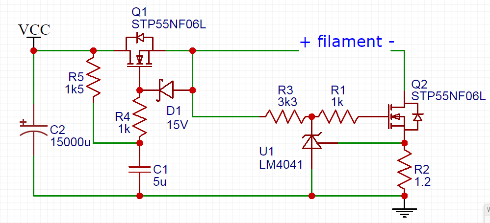
Rod Coleman also has a very interesting approach to DHT filament regulation. You can find boards/kits for sale here (no commercial interest, just admiration for the design).

coleman regulator

This circuit feeds the filament from the ‘positive’ end with a gyrator, also known as a cap multiplier in this configuration. The transistor Darlington pair sees a low-passed capacitor at its base and works to amplify this smoothed signal at its low impedance emitter (effectively making the cap seem much bigger than it really is). This doesn’t regulate voltage because the gyrator doesn’t have a fixed reference, but it does reduce ripple drastically.

The ‘negative’ end of the filament is connected to a constant current sink. This is a ring-of-two CCS design which will have a lower operating voltage requirement than a cascode CCS or many ICs. Because our current is relatively high, low dropout voltage is a benefit in reducing overall power dissipation.

The filament is fed a low ripple voltage with a CCS setting the current. It’s simple, but reports seem universally positive for Coleman’s regulator approach. Whether filament bias or cathode bias, the filament supply should be left floating (it finds ground through the bias resistor or grounded cathode).

There’s little reason to reinvent the wheel here as far as I can tell. Although I’m still casually reading, I’ll more than likely try one or more of the above approaches to powering the filaments in my upcoming #26 project. More to come on this project as parts arrive and the ideas ferment.

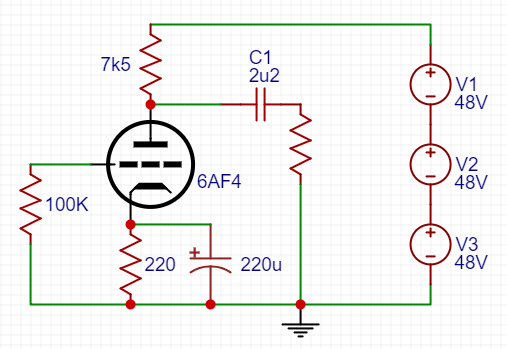
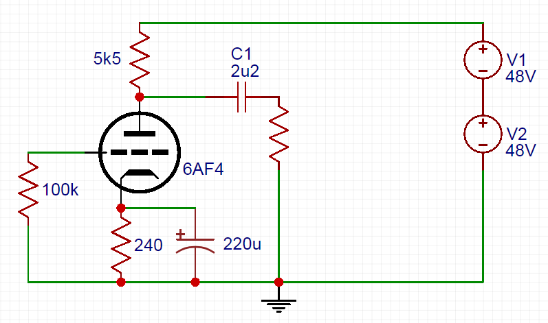
P.S. here’s a FET version of the same gyrator-CCS one-two punch:

FET filament reg