Simple discrete CCS

You’ve already read the CCS and loadlines page that discusses how a constant current source affects a tube’s behavior. You have also seen CCS’s made from depletion mode MOSFETs and LM317’s in projects like the Papa Rusa and El Estudiante (respectively). These don’t go into the actual operation of a CCS, so here’s a post illustrating a simple discrete CCS.

A NPN bipolar junction transistor (BJT for short) is a three terminal device, like a tube triode:

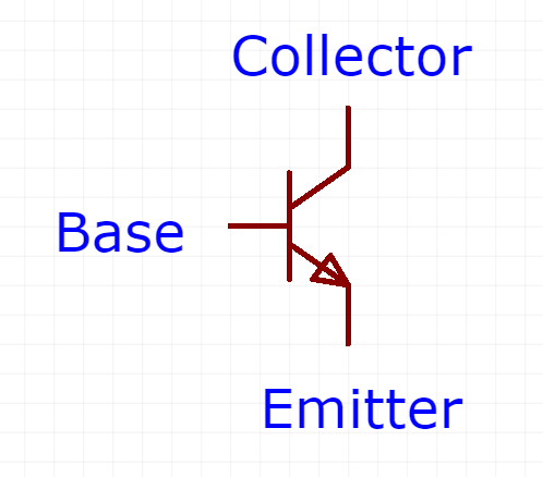
The BJT collector, base, and emitter are roughly analogous to a tube’s anode, grid, and cathode. With a vacuum tube, we set a bias between the grid and cathode and generally the grid is held at some negative voltage potential relative to the cathode. With a NPN BJT we set a bias between the base and emitter and generally the base is at a positive voltage potential relative to the emitter for current to flow.

With a tube, current flow is limited by a cathode resistor (also serving to set bias). We can make a simple CCS out of a triode using a cathode bias resistor and referencing the grid to ground. The impedance at the anode (where we’d connect the load) is the anode impedance plus the impedance of the cathode resistor multiplied by Mu + 1. In other words:

Z = Rp + Rk * (Mu +1)

The tube CCS requires a fair amount of voltage across it to function. This limits the practical applications and is probably why you really don’t see it very often (and it’s usually pentodes used as a CCS when you do). The impedance seen by the load and the current handling are also pretty low compared to what can be achieved with evil, no good, dirty, rotten solid state.

Like the triode above, we can use a resistor in the emitter of a BJT to set the current at the collector. The difference here is that the base needs to be positive relative to the emitter for it to be ‘open’ (letting current flow). This means we cannot use ground as the base’s DC reference like we did with the triode:

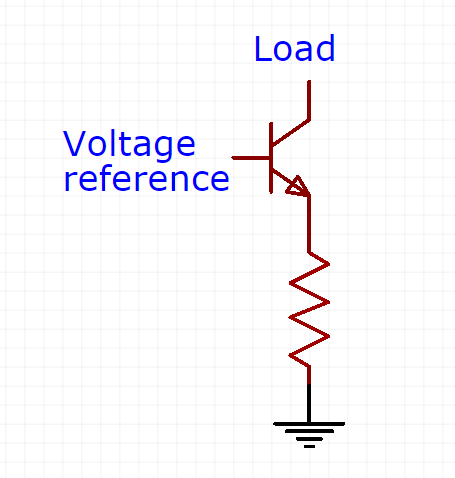
The humble LED has a stable voltage drop that varies little with the amount of current through it. They also tend to exhibit very low noise. These qualities make LEDs nice voltage references for transistors (as well as cathode loads for tubes).

We feed the LED through a resistor (R2) from a voltage source (B+ or other auxiliary supply) to limit the current. The amount of current through the LED is not critical, typically in the neighborhood of 5-15mA. The voltage drop of the LED varies with type and color, but red LEDs typically average about 1.6V. This voltage drop is the voltage reference for the base of the BJT.

For the transistor to pass current, we need to turn it on by biasing the base positive relative to the emitter. The voltage required to “turn it on” is often referred to as the base-emitter drop and is in the neighborhood of 0.6-0.7V. With a red LED reference of 1.6V and a base-emitter drop of 0.6V, we would have about 1V across the emitter resistor (R1).

The value of the emitter resistor determines how much current passes through the BJT. We find the resistor value needed for our target current with regular old Ohm’s Law. If we want to set 2mA through the CCS, we need an emitter resistor of:

R = V / I

500 ohms = 1 volt / 0.002 amps

In practice, the emitter resistor may be replaced with a trim pot to allow for an adjustable current. The load impedance created by the transistor CCS is approximately the dc current gain (hfe) multiplied by the emitter resistor. For small TO92 transistors (e.g. PN2222), current gain can be a factor of a couple hundred. That means with a voltage drop of only a few volts, we can create an impedance of 100k+!

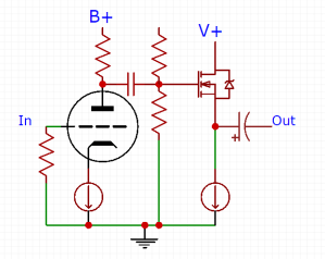
The above simple discrete CCS would work in the cathode of a tube stage, but we can also use PNP transistors in the same way as anode loads:

The above generic circuits require suitably rated parts to work in real life. The resistor feeding the LED often needs a high voltage and power rating if it is connected to B+. The transistor may also need a high voltage rating and/or a heatsink. In practical terms though, these are as simple as they look and make a good introduction to the inner workings of constant current sources/sinks. A common and quick improvement to the above examples is to cascode two transistors, multiplying the current gain, and easily pushing the impedance well over 1M.

The LR8 in tube circuits

The high voltages required for many tubes rule out or complicate integrating many otherwise useful solid state parts. The LM317 and TL431 are ubiquitous regulator solutions, but they’re limited to 36-37V. Too low in most cases for a simple one-chip B+ supply.

The LR8 (datasheet here) is a lesser-known TO92 high-voltage regulator. The maximum input voltage is 450V and the minimum dropout voltage is 12V. Output voltage is set with a simple resistor divider. With just a handful of passive parts, you can use the LR8 to create a regulator for tube B+:

LR8 simple

As a little TO92 device, dissipation and current are limited of course. The circuit above might work for something like El Matemático (one per channel), but higher current applications require the addition of a pass device. In this case, a MOSFET uses the LR8 as the voltage reference on the gate, in turn setting the source voltage just a few volts lower: LR8 compound

While zeners and VR tubes also make a good gate reference in similar series regulator applications, they come in fixed values. The great thing about the LR8 is that we can set the output to any value we like, alleviating the need to keep a bunch of zeners or VR tubes on hand.

I have PCBs of the series circuit made up and will be testing in an upcoming build. In the meantime, this isn’t so complicated that it couldn’t be done on a proto board.

Board prototypes on the way

Although I love wiring tubes point to point, there are times where some TO92 or other small parts are needed. These often benefit from short leads, making layout and spacing critical. One of my upcoming projects makes these kinds of demands. Having dealt with death-by-soldering iron and oscillations when trying to point to point wire small parts in the past, I decided to try my hand at some small boards to make things easier on myself.

I still believe that for tubes there are real advantages to p2p wiring and turret strips. After all, they’re fairly large robust parts and part of the fun of building something is scavenging enclosures, optimizing the layout and grounding, etc. But where a small solid state circuit is needed, a modular board is great to have.

More to come on these boards once I’ve been able to test them and use them in builds.

ccs board finalreg board finalshunt board final

Class A FET power buffers

I’ve been kicking the hybrid amplifier can down the road for quite a while. In essence, I’m looking to do a bigger EL Estudiante. An amp capable of driving speakers to a dozen or two watts using a MOSFET follower output stage for current gain and a tube handling the voltage gain. While this is not especially difficult on paper, making something that is an interesting and practical alternative to tube output stages is not necessarily so straightforward.

On one hand, one should consider the target user. Most tube enthusiasts do not need so much power, so we can bias in Class A and avoid a whole lot of AB headaches and worry about bias adjustment, crossover distortion, etc. This has to be balanced against heatsinking and thermal considerations, of course. Coming from the world of tubes, our audiophile anti-bodies have already pretty well encysted any commonsensical tendencies we may once have harbored, but the smoke point of drywall hasn’t changed. That is to say solid state does not magically make Class A cool, efficient, or pragmatic, but why make something hotter, more wasteful, and more burdensome than vacuum tech? We’re hoping to make something that is more than the sum of its parts.

ccs load se

The Aikido Hybrid 16W SE by John Broskie has about as much power as most probably need. Sixteen is two to the fourth watts, so four times three decibels per doubling of power for a 12db increase over nominal speaker rating (eg your 90db speakers peak at 102db). The quiescent current is a very serious 2A. It is a single-ended MOSFET source-follower loaded by a current source. There’s little not to like other than the coupling caps (contrast this with output transformers for AC coupling in full tube amps). See also Rod Elliott and Pavel Macura’s CCS-loaded follower here.

inductor load se

We can make single-ended more efficient with an inductive load.  Just like a choke load with tubes (eg Luciernaga), an inductive load on a MOSFET lets it swing voltage past the power rails.  The MoFo is an example of a single-ended source-follower MOSFET with a simple passive choke load (50-150mH and very low DCR). This is much more efficient than an active CCS in an absolute watts dissipated sense (note the much lower supply voltage), but chokes ain’t cheap and you still need a good dose of current.

diode bias pp

If you want to lower the quiescent current needed, but stay in Class A, push-pull source-followers are the way to go. Papa Pass’s F4 power buffer does exactly this to cut the quiescent current needed in half. The need to match FETs may be unappealing, but compared to his single-ended F3, F2, or Aleph J, the power delivery into 4 ohm loads is much improved. Note Broskie suggests the same push-pull MOSFET approach (with a different biasing scheme) in the Moskido amp design.

Any of the above would probably sound pretty good: like a tube feeding a very transparent solid state amp. If the amount of power you need is modest (and it probably is if you’re a tube enthusiast), these approaches have made very nice speaker amps. Hopefully I’ll have my own design to contribute soon. MOSFET followers would also make a great multi-watt amp for low sensitivity and low impedance headphones, like the HIFIMAN HE-6.

The HE-6 are rated at a sensitivity of 83.5db at 1 mW.  With 1000x more power (1W), we’d make 103.5db (a 20db increase). Around 5W input makes it a cool 110db. Coincidentally, this is the power rating of the amp HIFIMAN recommends as a pairing.  The HE-6’s 50 ohm impedance lowers the quiescent current needed in a MOSFET output stage, though still requires a voltage rail high enough to prevent clipping. A quick approximation for voltage would be:

power = Vrms²  / impedance

5W x 50 ohms = 16 Vrms²

16 Vrms x √2 x 2 = 46 Vptp

So about a 48V power rail (or +/- 24V) gets us in the neighborhood. Doing the same for current:

power = Irms² x impedance

5W / 50 ohms = 0.32 Irms²

0.32 Irms x √2 = 0.5 Ipeak

We only need about a 48V power rail and 0.5A quiescent current per channel to get us 5W into a 50 ohm load if using a CCS loaded MOSFET. If we choke load, cut the 48V in half. If we use Class A push pull, cut the current in half. The heatsinks aren’t going to be tiny, but a desktop size amp isn’t out of the question.


Ode to the ST-70

dynaco st70.png

The ST70 is a beautiful and historic amplifier (and surprisingly compact if you see one in person). It’s also the best selling power amp of all time (at least so says Wikipedia). All things Dynaco inspire much talk here around the water cooler at the WTF Amps institute of higher learning about vacuum tube stuff. Here are some loosely organized tidbits and thoughts on amplification!

Generalized Topological Design Trends in Discrete Amplification

Forget for a moment that some amps are made with tubes while others are made with transistors. Deep down in their vacuum or silicon hearts they are really both just simple three-pin devices used to accomplish the same thing (gain). Forget all the audio-speak we abuse in our efforts to approximate the many facets of circuit performance. Forget the preconceptions we file away in our minds under “T” for tube or “S” for solid state. We aren’t thinking about tubes or transistors, right? Good.

To SE or PP (tee-hee)

Beyond all other aspects, the amplifier topology choice that impacts a design the most -in performance, efficiency, and cost- is whether the amplifier will be single-ended or differential. The difference can be boiled down to whether the amplification devices handle the entire signal through to the output (single-ended) or “split” the signal phases and re-combine them at the output (differential). Differential amplifiers are sometimes also referred to as push-pull. There is no such thing as balanced amplification, but that’s another discussion.

Single-ended amplifiers tend to be more inefficient in both a power consumption and economic sense. Because they are Class A by necessity, they dissipate more heat per watt of amplification. Single-ended amplifiers need a squeaky clean power supply to achieve a respectable noise floor because they do not benefit from the same kind of ripple rejection as differential amplifiers. They tend to produce more distortion, but the distortion that they produce usually has an even-order-dominated harmonic spectrum. Studies say even-order distortion harmonics are less offensive to most listeners.

In contrast, differential amplifiers produce less distortion when designed well, but what they do produce is dominated by odd-order harmonics, which are less pleasing to most listeners. Differential amplifiers are capable of far more efficiency than single-ended amplifiers because both output phases do not need to be “on” all the time. By nature, differential amplifiers reject power supply noise because they only amplify the difference between the phases and any power noise appears equally in both.

/r/outoftheloop

The distinction between single-ended and differential is the most fundamental taxonomy that can be applied to amps. The next most important design choice with regards to the circuit and its behavior is whether the amplifier will be open-loop or closed-loop. A closed-loop amplifier injects a portion of the output back into the circuit in order to correct non-linearities created by the act of amplifying with non-imaginary devices. This requires extra gain from the amplifier to be spent on suppressing these distortions. An open-loop amplifier is able to get by with less overall gain and enjoys more polite clipping behavior at the expense of generally higher THD. We are very deliberately avoiding the term ‘negative feedback’ here, by the way.

If you’re following along, you see that less-efficient single-ended amplifiers with less-objectionable distortion spectrum might naturally gravitate towards open loop circuits. Furthermore, you can imagine that more efficient differential amplifiers, with power to spare but a less pleasing distortion spectrum, are logical candidates for closed loop circuits. Your powers of comprehension do not fail to impress, dear reader. In practice a blend of single-ended and differential, open loop and closed loop, choices are made at the stage/component level in order to balance the relevant strengths and weaknesses, but the broader structure of amplifiers is usually one or the other.

WTF were we talking about again?

I’m going to tell you a secret now. Please do not react too loudly or cause a commotion. Come closer… Single-ended, differential, open loop, and closed loop has nothing to do with whether an amp uses tubes or transistors. Yes, that’s quite something isn’t it? While it’s true that historically certain devices and topologies are strongly associated one to another, this is a question of device availability coinciding with design trends and market demands, not choices dictated purely by the devices used.

This brings us back to the topic of the Dynaco ST-70. This is a closed loop differential amplifier running in Class AB, much like the earlier Williamson or Leak tube amplifier designs. The overall topology is not much different from current Class AB transistor amplification because these solid state amps are simply a continuation of the same design trend (AB differential, closed loop). While today we associate tubes with single-ended open loop design and transistors with differential closed loop design – and all the baggage these topologies drag about – the reality is that performance has more to do with circuit choices than with the devices used.

The ST-70 was in some ways a pioneer. Though it was not the first of its kind, it was the standard bearer of the contemporary design values. Today we prize much of the ST70’s topological progeny in solid state Class AB (whether integrated on a chip or built with discrete components) but we also revere designers such as Nelson Pass who is charting his own course through both open loop single-ended transistor and Class A low feedback differential amplification. Amplifier design is not so much a timeline as it is a spectrum; the limits to what constitutes good amplification (subjective as that may be) are found not in the parts choices, but in the creativity of the designer.

TL;DR: Design, not device, makes the amp.

Here’s Dan Fraser’s write-up on the launch of the modern ST-70 series 3 (Dynaco was purchased by Radial Engineering in 2014)

Guest Post at Audio Primate: JDS Labs CMOYBB Review

023

One part market research and two parts DIY hobby service: click here for another review of a small solid state headphone kit/board at Audio Primate. JDS Labs has done an excellent job with this kit. Everything is clearly labeled, the board is good quality, and the documentation is excellent.

If you want a place to start with DIY amps and line-level gear, look no further than the classic CMOY.