Except one of the pesky caps from the BOM. Lots of little baggies for such a small board. Good thing I’ve been eating my carrots.
Coaster and parts have arrived


tubes for the noobs in us all
Except one of the pesky caps from the BOM. Lots of little baggies for such a small board. Good thing I’ve been eating my carrots.
If you spend enough time haunting DIY tube amp websites and books, you will inevitably come across the theme of direct-coupled tube circuits. N-type and p-type transistor sandwiches make direct coupled circuits almost trivial. Tubes, which are “n-type” only, are not quite so simple to marry anode to grid. And yet the siren sings, drawing in the adventurous tube spirits.
“Why should we want to direct couple in the first place?” you ask, your socratic gland tingling. Many solid state amplifiers take advantage of the direct coupling to increase the levels of negative feedback. With tubes, we’re often more interested in maximizing the inherent linearity of triodes in open loop Class A amplification (but for a good counter example, see Jones’s Crystal Palace in Valve Amplifiers 4th ed).
Ostensibly, eliminating a coupling capacitor or transformer leaves less in the signal path between input and output, making whatever you are building more transparent (if you consider caps to be a significant source of coloration). Eliminating a coupling capacitor also removes a potential source for blocking distortion (if you are prone to driving amps to clipping, though a cap-bypassed cathode resistor can still cause you problems). In my opinion, the most compelling reason to direct couple is that it makes A2 (positive grid bias) operation a possibility.
Following are some (mostly untested) scratch-pad ideas and notes for “simple” direct-coupled SET amplifiers.
Fig 1: Simply using an abnormally large cathode resistor under the output tube raises its cathode above the anode voltage of the driving stage. This dissipates a lot of extra power in the output section and doesn’t really contribute anything to A2 operation. Still, a fun party trick.

Fig 2: Using a resistor divider to lower the dc voltage seen by the output tube’s grid. This reduces the gain of the first stage and probably still requires you raise the cathode of the output stage (see Jones for good reading on this).

Fig 3: The Free Lunch style of choke loading the driving stage is as nifty as it is temperamental (in my experience). You are still dissipating power in the cathode of the output tube. See also Loftin-White variations discussed at TubeCAD.

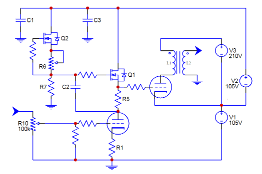
Fig 4: Currently simmering on my back burner, a MOSFET gyrator sets a reliable voltage on the grid of the output tube and its low output impedance enables A2 operation. Rather than raising the cathode by dissipating power in a bias resistor, the cathode is raised by a separate power supply (must be rock solid). Additional stacked supplies provide B+ for the output tube and driving stage.
It should be pointed out that direct coupling will almost always require some extra calculating, measuring, and adjusting of whatever you build (you get a glimpse of this with the El Estudiante cathode resistor trial and error). You’re also likely to pigeon hole a direct coupled circuit to very specific tubes, not to mention bias points (which must be maintained). But despite these warnings, once you’ve heard the legend of the circuit without caps, it may already be too late.
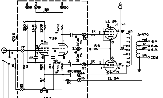
The ST70 is a beautiful and historic amplifier (and surprisingly compact if you see one in person). It’s also the best selling power amp of all time (at least so says Wikipedia). All things Dynaco inspire much talk here around the water cooler at the WTF Amps institute of higher learning about vacuum tube stuff. Here are some loosely organized tidbits and thoughts on amplification!
Forget for a moment that some amps are made with tubes while others are made with transistors. Deep down in their vacuum or silicon hearts they are really both just simple three-pin devices used to accomplish the same thing (gain). Forget all the audio-speak we abuse in our efforts to approximate the many facets of circuit performance. Forget the preconceptions we file away in our minds under “T” for tube or “S” for solid state. We aren’t thinking about tubes or transistors, right? Good.
Beyond all other aspects, the amplifier topology choice that impacts a design the most -in performance, efficiency, and cost- is whether the amplifier will be single-ended or differential. The difference can be boiled down to whether the amplification devices handle the entire signal through to the output (single-ended) or “split” the signal phases and re-combine them at the output (differential). Differential amplifiers are sometimes also referred to as push-pull. There is no such thing as balanced amplification, but that’s another discussion.
Single-ended amplifiers tend to be more inefficient in both a power consumption and economic sense. Because they are Class A by necessity, they dissipate more heat per watt of amplification. Single-ended amplifiers need a squeaky clean power supply to achieve a respectable noise floor because they do not benefit from the same kind of ripple rejection as differential amplifiers. They tend to produce more distortion, but the distortion that they produce usually has an even-order-dominated harmonic spectrum. Studies say even-order distortion harmonics are less offensive to most listeners.
In contrast, differential amplifiers produce less distortion when designed well, but what they do produce is dominated by odd-order harmonics, which are less pleasing to most listeners. Differential amplifiers are capable of far more efficiency than single-ended amplifiers because both output phases do not need to be “on” all the time. By nature, differential amplifiers reject power supply noise because they only amplify the difference between the phases and any power noise appears equally in both.
The distinction between single-ended and differential is the most fundamental taxonomy that can be applied to amps. The next most important design choice with regards to the circuit and its behavior is whether the amplifier will be open-loop or closed-loop. A closed-loop amplifier injects a portion of the output back into the circuit in order to correct non-linearities created by the act of amplifying with non-imaginary devices. This requires extra gain from the amplifier to be spent on suppressing these distortions. An open-loop amplifier is able to get by with less overall gain and enjoys more polite clipping behavior at the expense of generally higher THD. We are very deliberately avoiding the term ‘negative feedback’ here, by the way.
If you’re following along, you see that less-efficient single-ended amplifiers with less-objectionable distortion spectrum might naturally gravitate towards open loop circuits. Furthermore, you can imagine that more efficient differential amplifiers, with power to spare but a less pleasing distortion spectrum, are logical candidates for closed loop circuits. Your powers of comprehension do not fail to impress, dear reader. In practice a blend of single-ended and differential, open loop and closed loop, choices are made at the stage/component level in order to balance the relevant strengths and weaknesses, but the broader structure of amplifiers is usually one or the other.
I’m going to tell you a secret now. Please do not react too loudly or cause a commotion. Come closer… Single-ended, differential, open loop, and closed loop has nothing to do with whether an amp uses tubes or transistors. Yes, that’s quite something isn’t it? While it’s true that historically certain devices and topologies are strongly associated one to another, this is a question of device availability coinciding with design trends and market demands, not choices dictated purely by the devices used.
This brings us back to the topic of the Dynaco ST-70. This is a closed loop differential amplifier running in Class AB, much like the earlier Williamson or Leak tube amplifier designs. The overall topology is not much different from current Class AB transistor amplification because these solid state amps are simply a continuation of the same design trend (AB differential, closed loop). While today we associate tubes with single-ended open loop design and transistors with differential closed loop design – and all the baggage these topologies drag about – the reality is that performance has more to do with circuit choices than with the devices used.
The ST-70 was in some ways a pioneer. Though it was not the first of its kind, it was the standard bearer of the contemporary design values. Today we prize much of the ST70’s topological progeny in solid state Class AB (whether integrated on a chip or built with discrete components) but we also revere designers such as Nelson Pass who is charting his own course through both open loop single-ended transistor and Class A low feedback differential amplification. Amplifier design is not so much a timeline as it is a spectrum; the limits to what constitutes good amplification (subjective as that may be) are found not in the parts choices, but in the creativity of the designer.
TL;DR: Design, not device, makes the amp.

This write-up will have two parts. The first (the PSU) is posted and hopefully I’ll have the amp write-up done shortly. This project is the most ambitious one I’ve written up for the site so please excuse the omission of some of the finer calculations and details.
Although the power supply is rather complicated, the amplifier will be pretty straightforward (pinky swear). The supply can be used with other amps and the amp can be used with other supplies, which is one of the reasons I decided to split it into two pages.

I added a short page on tube rolling and how it may or may not affect an amp. It will probably still get a little polish and maybe some elaborations, so please let me know if it leaves you with more questions or confusion!

This poor radio has seen better days and doesn’t quite live up to modern safety standards with regards to mains electricity. But the look is great and there’s generous space inside for a small tube amp. Because the enclosure must be allowed to vent for the tube amp to dissipate heat, the speaker (which I also plan to modernize) will be a small challenge. This is a great candidate for a DIY tube radio restoration.
Probable features:

Here’s a spreadsheet I built for calculating RIAA values in two stage tube phono preamps. When comparing results to other published designs using the same filter network, everything looks correct (within a few percent due to estimation of Rp). I used this sheet for El Matématico.
If you want to estimate values for something like a CCS loaded stage, you can set Rload on the appropriate stage to 1M or thereabouts. If you’re looking at using a cascode, mu follower, SRPP, etc 1st stage, you’ll need to make sure the Zout figure the sheet uses (cell I6) reflects the Zout of the topology because it is used to calculate R1. Same thing goes for cell I3 (Miller capacitance of 2nd stage) if you use a gain stage after the filter that affects this (cascode, grounded grid, etc).
Go build a phono preamp!

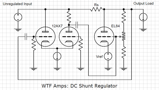
Although I love me VR tubes something fierce, they aren’t in current production and I’d like a simple (or well as simple as possible, I guess) shunt regulator alternative for things like phono preamps or line stages (20mA of load current or thereabouts).
This shunt regulator uses an EL84 for the heavy shunt lifting and a 12AX7 differential amplifier (using non-inverting output) to amplify any ripple on the output (which the EL84 ‘cancels’ across Rs). Quick calculations look like about 100V of headroom would be nice to have so rectified 250Vac with the shunt should be good for about 250Vdc regulated output.
Update: Putting the differential amplifier before the shunt will unload it a bit and provide more B+ headroom for higher gain.
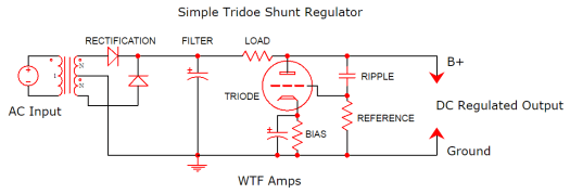
I’ve been doing some reading on tubes in shunt regulator power supplies lately (lots of great articles on TubeCAD including this one). I’m planning to incorporate one in an upcoming build. In operation, this isn’t too different from the VR regulator power supply in my Matemático Phono Preamp, but a shunt regulator with a triode would have an adjustable output and might afford even better ripple rejection.
My recent series regulator project is another example of power supply regulation.

Q:
What is your opinion on rectification?
A:
