
If you spend enough time haunting DIY tube amp websites and books, you will inevitably come across the theme of direct-coupled tube circuits. N-type and p-type transistor sandwiches make direct coupled circuits almost trivial. Tubes, which are “n-type” only, are not quite so simple to marry anode to grid. And yet the siren sings, drawing in the adventurous tube spirits.
“Why should we want to direct couple in the first place?” you ask, your socratic gland tingling. Many solid state amplifiers take advantage of the direct coupling to increase the levels of negative feedback. With tubes, we’re often more interested in maximizing the inherent linearity of triodes in open loop Class A amplification (but for a good counter example, see Jones’s Crystal Palace in Valve Amplifiers 4th ed).
Ostensibly, eliminating a coupling capacitor or transformer leaves less in the signal path between input and output, making whatever you are building more transparent (if you consider caps to be a significant source of coloration). Eliminating a coupling capacitor also removes a potential source for blocking distortion (if you are prone to driving amps to clipping, though a cap-bypassed cathode resistor can still cause you problems). In my opinion, the most compelling reason to direct couple is that it makes A2 (positive grid bias) operation a possibility.
Following are some (mostly untested) scratch-pad ideas and notes for “simple” direct-coupled SET amplifiers.
Fig 1: Simply using an abnormally large cathode resistor under the output tube raises its cathode above the anode voltage of the driving stage. This dissipates a lot of extra power in the output section and doesn’t really contribute anything to A2 operation. Still, a fun party trick.

Fig 2: Using a resistor divider to lower the dc voltage seen by the output tube’s grid. This reduces the gain of the first stage and probably still requires you raise the cathode of the output stage (see Jones for good reading on this).

Fig 3: The Free Lunch style of choke loading the driving stage is as nifty as it is temperamental (in my experience). You are still dissipating power in the cathode of the output tube. See also Loftin-White variations discussed at TubeCAD.

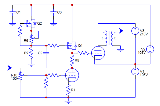
Fig 4: Currently simmering on my back burner, a MOSFET gyrator sets a reliable voltage on the grid of the output tube and its low output impedance enables A2 operation. Rather than raising the cathode by dissipating power in a bias resistor, the cathode is raised by a separate power supply (must be rock solid). Additional stacked supplies provide B+ for the output tube and driving stage.
It should be pointed out that direct coupling will almost always require some extra calculating, measuring, and adjusting of whatever you build (you get a glimpse of this with the El Estudiante cathode resistor trial and error). You’re also likely to pigeon hole a direct coupled circuit to very specific tubes, not to mention bias points (which must be maintained). But despite these warnings, once you’ve heard the legend of the circuit without caps, it may already be too late.
