Line stage + phono build underway

In a recent post I set a goal for myself of creating a couple of preamp designs that included both line stage and phono preamp circuits. The first of these builds is now underway! Because of the number of input and output jacks as well as switching and volume controls, I’m using a different style chassis than the all-wood apron approach in most of my builds. The face plate and rear of this enclosure are aluminum with wood (walnut here) used as accent panels on the sides.

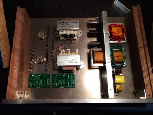
I’m emphasizing the sleeker look by mounting all of the transformers inside the chassis. The power supply is mounted to a section of aluminum c channel that also serves to section off all of the AC power from the rest of the chassis (which will carry sensitive signal circuits). So far so good. We’ll know if the approach to shielding and layout is effective once it’s powered up and playing. Placement for the signal portion will be finalized after I’ve mounted the front panel controls into the 3/8″ aluminum flat. I expect that to be a bit of an adventure…

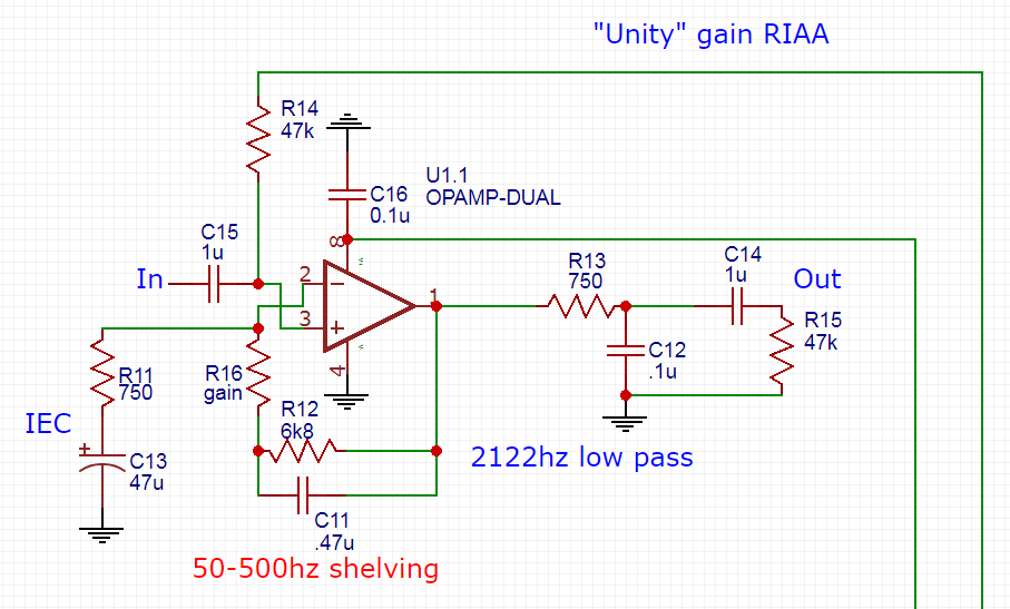
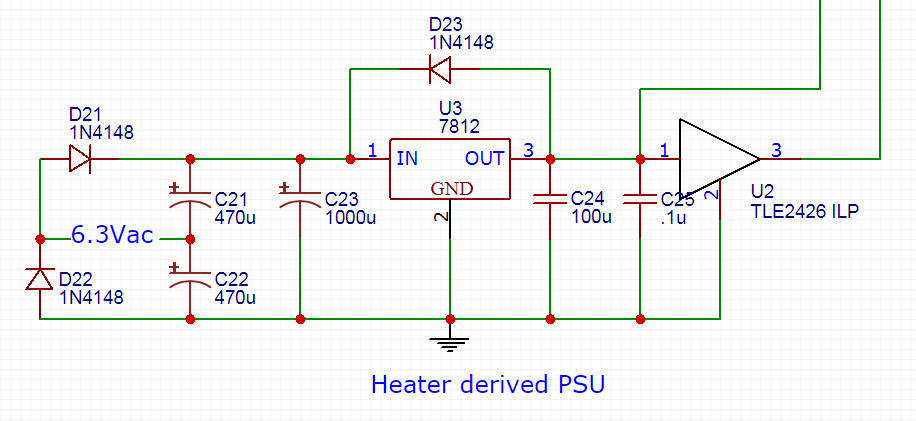
The generic circuit for this build is below (final values will be published once it’s tested). Tracing the path of a phono signal: the resistor loaded input stage feeds the RIAA correction filter which feeds a gyrator loaded output stage. I’m using a gyrator as a flexible load to allow for tube swapping as well as a low output impedance device to effectively drive the follow control that follows after the selector switch. The volume control feeds a transformer loaded 6H30.

The Edcor GXSE 15k:600 output transformers are an experiment here. Reading through others’ experiences and measurements, I think the 6H30 is going to be a suitable driver with good bandwidth if it’s given enough current. I expect to do some experimenting with loading the secondary.

All in all, this will be all 9-pin current production tubes and parts. If the execution works out as well in real life as it does on paper, it will be a great, relatively-affordable preamp build.

New batch of boards!

Another batch of boards just arrived for some of my upcoming projects and experiments. These include:

  • MOSFET driver for A2 output stages
  • FW rectifier+voltage doubler combo on a compact board
  • MOSFET cap multiplier and CCS for DHT filaments
  • Shunt cascode boards v2 (slight layout changes to previous version)
  • MOSFET “gyrator” anode load
  • Low voltage bipolar supply (LM317 and LM337) for opamps

Some of these will be used for upcoming phono and line-stage builds while others are daydreams that I’ll get around to eventually 🙂

Reminder: extra PCBs are available for free or for purchase to my Patreon supporters

Combining Line Level and Phono

I love boxes with tubes sticking out as much as the next DIYer. Generally, the more boxes, the better in my mind. In practical domestic life however, lots of specialized chassis (beautiful as they may be) don’t always translate well to limited space or the aesthetic considerations of cohabitants (AKA: WAF).

The phono and line-level functions are a good place we can look to consolidate our pretty enclosure collection. The voltage levels are manageable, the current requirements are usually low, and the tubes used are not especially large (in most cases). The question then is how best should we integrate something like a phono preamp and a line level preamp.

The schematic above gives an idea of the approach I intend to take for this kind of phono+line level project. A phono signal travels through an RIAA section sandwiched by two gain stages. This is attached to one input of a three way switch; the other two inputs at the switch can be used with a CD player, streamer, or other source of your choice. The output of the switch feeds a volume control, which in turn feeds a transformer-loaded single ended output stage.

Using a transformer on the output allows us to set a nice low gain for the line level section. Although a CD player probably won’t need it, some vinyl recordings and cartridges benefit from a small boost (e.g. 2x voltage gain, 6db). The transformer also allows us to step down our output impedance, much like the cathode follower in the Muchedumbre project. Of course, line level output transformers that can be used in a series feed configuration are not usually cheap.

I have a pair of Lundahl 1660 AM transformers to be used in this project. These run around $500 a pair (via kandkaudio.com). They are a well-known transformer for exactly this application. I have also purchased a pair of Edcor GXSE 15k:600 transformers ($40 a pair) as a budget-minded comparison. The transformer ratios are similar (4.5 or 5 to one) and both can be used in series-feed applications. While the Lundahl datasheet is very detailed, you may have some trouble getting inductance and DCR specifications from Edcor.

This is a tale of two preamps. I intend to design and build two all-in-one preamps with the same overall topology, but different tubes and parts. One preamp will be built using NOS tubes and high-end parts, while the other preamp will be built using current-production tubes and every-man components. I’m very excited to hear how the two projects compare and to be able to publish more than one option for people looking for an all-in-one preamp project.

More to come on this topic as I work-out the circuits and parts choices!

Opamp + tube RIAA board art

A recent discussion on diyaudio.com reminded me of the opamp-based RIAA idea I shared last summer. It turns out that someone else has done something similar and reports very good results. Koifarm was after a more integrated build with phono, streaming, and line level all in a box, but the basic idea of using an opamp to perform the RIAA corrections and a tube to provide some/all of the voltage gain is the same. We differ just in how it’s integrated: I’m after a simple RIAA module with outboard tubes while Koi was going for an all-in-one.

Here’s where I’ve landed so far on a board to contain the opamp bits and bobs:

The opamp runs from the 6.3Vac heater winding that would be included on any tube-centric power transformer, meaning there are no special windings or an extra transformer to power the solid state section. The output of the RIAA module would be fed to a simple tube gain stage of your choice. Here’s a grounded cathode application, but keeping the tube off the board means there’s tons of flexibility.

So, will it work? Koifarm thinks so and he’s a pretty prolific phono preamp builder. I’ve also already tested the same RIAA correction scheme in the battery powered phono project. I’m saving up a few designs to place a board order, but I’m hoping this RIAA module would make for a relatively simple and fun build this year.

Phono Preamp Heaters

Heater supplies, even with indirectly heated tubes, are a potential source of hum with high gain circuits like phono preamps. In a grounded cathode gain stage, the tube will amplify any signal it sees between the grid and the cathode. The tube doesn’t particularly care if that is an audio signal or an induced signal from some other part of the build. Indirectly heated tubes have a cathode sleeve around the filament heating it. The close geometry creates a happy little environment for coupling between the two. Eliminating this source of noise may require running heaters on DC rather than AC.

Here’s a simple schematic adapted from something Eli Duttman suggested for his modified RCA phono preamp:

12V dc heaters

This circuit (now on a PCB waiting for a phono build) uses a voltage doubler to turn a common 6.3Vac input into ~16Vdc which is then regulated to 12Vdc by a LM7812. The regulator is limited to 1.5A, but this is probably enough for any sane phono preamp’s heater demands (the pair of 12AX7 in the El Matemático require only 0.3A). This is one way of producing a DC heater supply.

I was recently discussing truly budget-oriented tube phono preamps with another builder. They proposed a $100 parts budget. The first place I’d look to start cutting costs in such a build is on the relatively pricey purpose-built power transformer needed for tube projects. In the case of a simple phono preamp like El Matemático, I’d try the following cost-cutting measures to the power supply:

  • Solid state 1N4007 rectification
  • Use a 115/230V isolation transformer like Triad N-68X in reverse (115V in, 230V out) for B+ @ $16
  • Use a 12V SMPS like Meanwell EPS-15-12 for heaters @ $7
  • Triad C-1X choke @ $10 and 220uF 350V+ caps @ $4 ea as CLC filter
  • Add RC to end of CLC filter to lower B+ and/or clean up residual ripple

We can greatly lower the cost of the B+ supply with the isolation transformer trick but it leaves us without a heater supply. Rather than a separate 6.3V or 12.6V transformer followed by a regulator circuit like the one shown above, I’d be tempted to experiment with a switch mode power supply like this Meanwell unit:

EPS15-12

The EPS15-12 supplies up to 1.25A at 12Vdc with 80mV of ripple (peak to peak). One need just supply it with mains voltage (85-264Vac). Power supplies like this switch at a very high frequency, which is why their transformers can be made so small. If that switching is audible, capacitively coupled between cathode and heater, additional filtering may be needed. Meanwell does not specify the switching frequency, but it’s very likely well above the 20hz-20khz range.

The final, potentially very affordable power supply, would look something like this:

very cheap psu

More Opamp RIAA

I’ve detailed some very simple RIAA math for opamps in a past post and even did a little PCB board project to test the calculations. The image above is from a Patreon patron who built a battery powered phono from the same batch of PCBs. I’m very happy with the beginner-friendly nature and sound of this 9V-powered opamp phono preamp. The $25 bill of materials is nice, too. But, it doesn’t have a tube.

Now that I know the RIAA math and combination of passive and active equalization works, I’ll move on to phase 2. The battery powered two-stage preamp has about 40db of gain (60db if you count what’s needed for the RIAA correction). What if we only asked the opamp to perform the equalization (without the extra gain)? Having an opamp-based RIAA correction module eliminates the pesky RIAA math, but still lets us roll our own for the rest of the circuit.

Here’s a quick take on the circuit:

unity riaa signal

This brings the low frequencies from the phono cartridge up and the high frequency levels down to create a ‘flat’ signal. All that’s left is to make up the 40db or so of gain to get around 1Vrms output. A stage or two of grounded cathode tube amplification is the simple answer. There’s no urgent need for high Mu here, either: just about any tube could work. Note R16 still allows for some gain to be set at the opamp, so even a single tube stage can get a little help.

Keeping with the theme of simplicity, the opamp circuit would be powered from a common 6.3V winding:

unity riaa power

The heater supply is voltage doubled and regulated with a common IC. We can also use a rail-splitter to create a virtual ground and improve the performance of the single-supply opamp circuit.

In theory, the above looks like a fun and simple way to build a tube phono stage. The tube type(s) used would be extremely flexible and the RIAA portion adds no real complication to the build. The builder needs only focus on their tube fundamentals.

This is on my short list for the next batch of test boards!

One little project comes to fruition

Early this year, I wrote a post about simple RIAA correction with opamps. Although it doesn’t involve tubes (yet), I recently completed a PCB-based build based on this post. This was both to test the calculations/theory as well as good practice in PCB design.

This ultra-simple phono preamp runs on just a pair of 9V batteries for power and utilizes a mix of feedback and passive EQ for RIAA correction. The batteries should last about 24 hours (playing time), but a bipolar AC-derived supply could be substituted without trouble. Gain is easy to adjust with just a couple of resistors (set at 40db in my build). The bill of materials runs about $25 with 5532 opamps and 5% tolerance WIMAs.

I’m planning on building a couple of these with coworkers and basing build instructions and any revisions on the experience. I do have some extra boards from this first run. Shoot me an email if interested!

A different way to RIAA

Phono preamps can be tricky builds due to the need for high gain with low noise. In tube land, linear high gain is not too difficult to achieve even without feedback. Power-supply-based noise can often be brute forced with extra filtering, actively regulated B+, and/or DC-powered tube heaters. High PSRR topologies (eg differential) also have an advantage in the early amplification stages.

stop stop its dead already.png
building phono PSUs be like

The place where most DIY builders are probably tripped up is the mysterious RIAA voodoo.  Because the physical limitations of the vinyl medium and cutting process require a limiting of low frequencies and a boosting of high frequencies, we need to reverse this EQ on the playback end in order to get back to ‘flat’ frequency response.

At it’s most basic, the RIAA equalization standard defines three frequencies: 50hz, 500hz, and 2122hz. We should have a 20db boost to 50hz, a -20db/decade transition from 50hz to 500hz, flat playback from 500hz to 2122hz, and a -20db/decade falling response above 2122hz. Note that 20db/decade is equivalent to 6db/octave, so these are not especially steep filters.

Splitting the RIAA requirements between low (<1khz) and high (>1khz), the low frequency manipulation requires at least 20db of gain from whatever device we are using. This type of EQ is commonly referred to as a shelving filter. The high frequency portion is only reducing the response and so it doesn’t require gain (ignoring the overall gain needed to get to line-level signals). This reducing of the high frequencies can be as simple as a first order low pass filter (just a resistor and a cap).

Tubes, with their fairly high output impedance and finite Mu, complicate RIAA frequency-dependent impedance calculations. Operational amplifiers, on the other hand, make filter maths fairly straight forward. Here’s an example:

opamp riaa

Starting at the output, the R1 and C1 combination form a simple low pass filter. Because the output impedance of opamps is so low, our equation need only involve the cap and resistor:

f(-3db) = 1,000,000 / (2 * Pi * CuF * R), rearranged as:

R1 = 1,000,000 / (2 * Pi * 2122hz * C1uF)

Begin with a tight tolerance capacitor (say 0.1uF) and you’ll get a resistor value that may come off the shelf or be created with a parallel/series combination (in the case of a 0.1uF C1, the resistor would need to be 750 ohms). The resistor appears in series with the output, so large values may require a high input impedance in the following stage.

The shelving filter created by R2, C2, and R3 appears in the feedback circuit of the opamp. Because we need 20db of gain, we know that the ratio of R2 to R3 should be approximately 10:1 (a 10x voltage gain difference corresponds to 20db). The 50hz point is set by the combination of R2 and C2 and is found with the same kind of capacitor reactance equation as the low pass:

R2 = 1,000,000 / (2 * Pi * 50hz * C2)

Again, start with the cap value because caps have fewer options and are harder to find in a tight tolerance. A 0.047uF cap gives an R2 of about 68k, meaning R3 should be about 6K8. The overall gain of the stage is further set by R-gain (Av = 1 + R3/R-gain).

So that’s a pretty simple way to EQ your vinyl to flat. More gain to bring the signal up to line level could be added by following the EQ/opamp stage with a ‘normal’ tube stage or two. Expect to see some more on this topic in a future project!

DIY tube RIAA calculator sheet

All-In-One RIAA Calculator

Here’s a spreadsheet I built for calculating RIAA values in two stage tube phono preamps. When comparing results to other published designs using the same filter network, everything looks correct (within a few percent due to estimation of Rp). I used this sheet for El Matématico.

If you want to estimate values for something like a CCS loaded stage, you can set Rload on the appropriate stage to 1M or thereabouts. If you’re looking at using a cascode, mu follower, SRPP, etc 1st stage, you’ll need to make sure the Zout figure the sheet uses (cell I6)  reflects the Zout of the topology because it is used to calculate R1. Same thing goes for cell I3 (Miller capacitance of 2nd stage) if you use a gain stage after the filter that affects this (cascode, grounded grid, etc).

Go build a phono preamp!