


Los Monos are coming

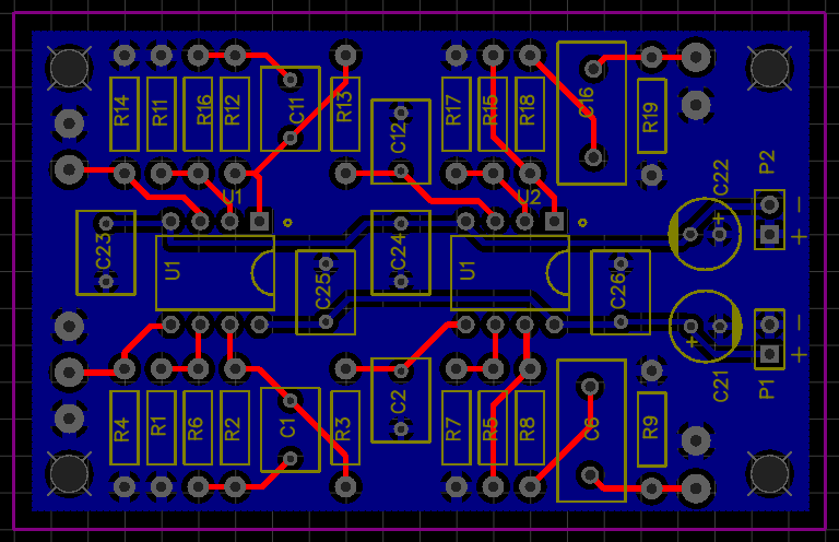
Here’s a sneak peak of the long-term push-pull project. The second monoblock is one cathode bypass capacitor away from being ready for playback. A bad tester tube took out the cap on one side during testing with a bang, but I’ll have replacements soon. Until then here’s the intro of the project write up.
The monkey on your back
Everything should be made as simple as possible, but not simpler.
-Einstein
There comes a time in every DIY builder’s life where he or she gets the urge to stretch beyond single-digit output power and single-ended amplification. There is no shortage of worthwhile projects to choose from: variations on Williamson, Mullard, or Dynaco push-pull topologies are easy to find discussed in forums and tweaked to compensate for modern parts. You can even find kits for something like the Dynaco ST-70.
When the double-digit power bug bit me I could not bring myself to abandon my usual no-feedback, triode output, class A comfort zone. This is the simplest (but not the only) path to good sound and my speakers are efficient enough. I’m also too lazy to do feedback math but that doesn’t mean open-loop, class A triode designs aren’t an engaging challenge. This build faced the following complications (which are common to many push-pull amplifiers):
- Class A requires healthy current in the output stage: this needs to be balanced in the output transformer to preserve inductance
- Two cascaded grounded cathode input stages is too much gain, but one stage is generally not enough
- The input stage must have low enough output impedance to drive the triode output tubes
For the most part, my solutions to the challenges strive for simplicity. As is often the case in tubes and life, simplicity in some areas is traded for complexity elsewhere. This push-pull amp has only two stages, the outputs are cathode biased, and it requires only three tubes per channel. To make this seeming simplicity possible, I used solid state helper circuits on PCBs. While these helper circuits are not technically complex, they drive up the parts count and require some measurement and adjustment.
Here is the conceptual topology for Los Monos:

Pictured is a two-stage triode output push-pull amplifier. The output stage is garter biased and the voltage gain and phase splitter stages are combined in a folded cascode long tail pair. This is all described below with a full schematic (showing lots more parts).
More of this write-up is on the way as soon as I’ve got both channels playing and glamour shots are taken!
Solid State Phase Splitters
The phase splitter is a critical step in a push pull (differential) amplifier. Because tubes don’t come in “p-types”, we feed the output devices signals that are inverted relative to one-another in order get one to push while the other pulls.
I’ve been finding solid state concertina-style phase splitters crop up here and there recently. A couple of days ago even the great Pete Millett got in on the action. Millett employs a JFET concertina splitter in his hybrid amp (a must-read, btw), but MOSFETs are also a good option for this application if you use parts with reasonable input capacitance.
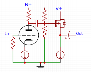
Here’s a push pull schematic I’ve been marinating that illustrates the MOSFET concertina:
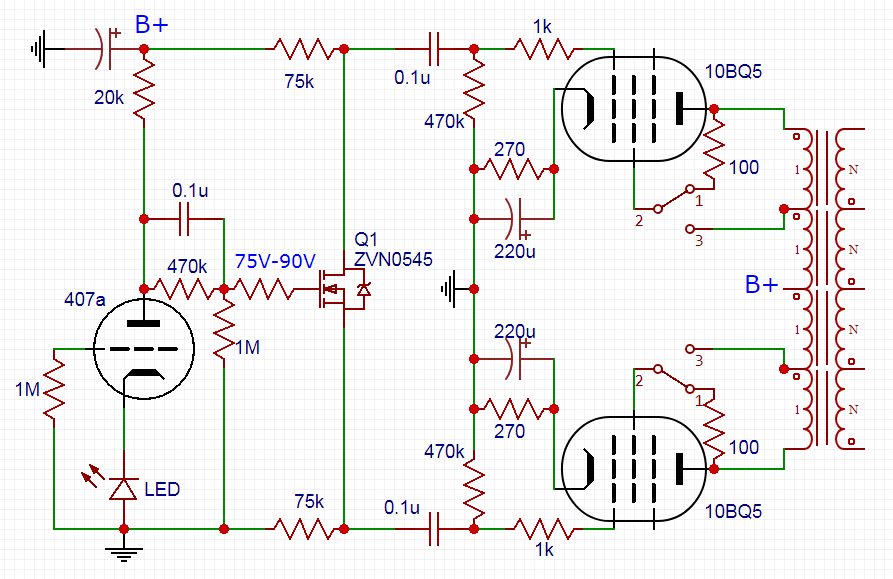
By using the MOSFET we’ve reduced the twin-triode count in a stereo push pull amp by one. The MOSFET will also let the splitter swing closer to the power rails, though in this particular case the 10BQ5 doesn’t really need a lot of voltage swing at its grid. The tubes shown are odd heater standards: 407A is 396A with a 20V heater and 10BQ5 is 6BQ5 with a 10V heater.
You can find a lengthier explanation of the RC step network between the 407A and MOSFET in Morgan Jones or buried in this diyaudio thread. In brief, the resistor divider sets the DC voltage at the gate of the MOSFET while the 0.1u cap bypasses the upper portion of the divider at AC frequencies so that we don’t lose any gain due to the divider.
The Nuvistor and Bob Katz’s Audio Blender (via Inner Fidelity)
Bob Katz has been writing a series of articles over at InnerFidelity for several years and they’ve recently taken a turn down a more experimental path. His most recent article details a device that mixes a transparent solid state signal and a Nuvistor signal biased to provide a distortion spectrum with just a small percentage of second harmonic. Check out his write up here!

A Nuvistor is a small metal and ceramic tube released by RCA just as transistors began supplanting vacuum tube technology in most electronics. They are a true vacuum tube with familiar triode operation and characteristics and an indirectly heated cathode. The most common Nuvistor in consumer electronics was the 6CW4 (high Mu) though there are several triode flavors and even a couple of tetrodes.

Because they were originally intended for radio and TV usage, Nuvistors enjoy very good bandwidth, low noise, and high gain (high Mu variants). The metal envelope is integrated with the basing and the tube plugs into what RCA dubbed the Twelvar base. You can probably guess how many pins that had. With the Nuvistor, RCA also introduced the RCA Dark Heater, a lower temperature filament that guaranteed higher stability and less AC leakage. Despite this innovation, most Nuvistor heaters require around 1W to light (e.g. 150mA @ 6.3V).
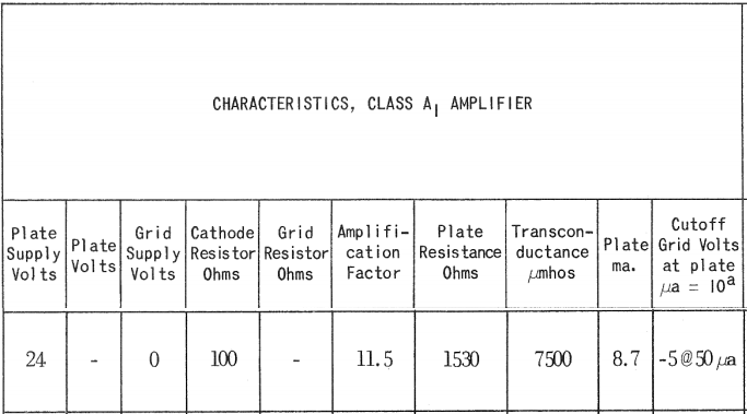
The 8056 used in Bob Katz’s project has the following characteristics:
And the following very respectable plate curves:
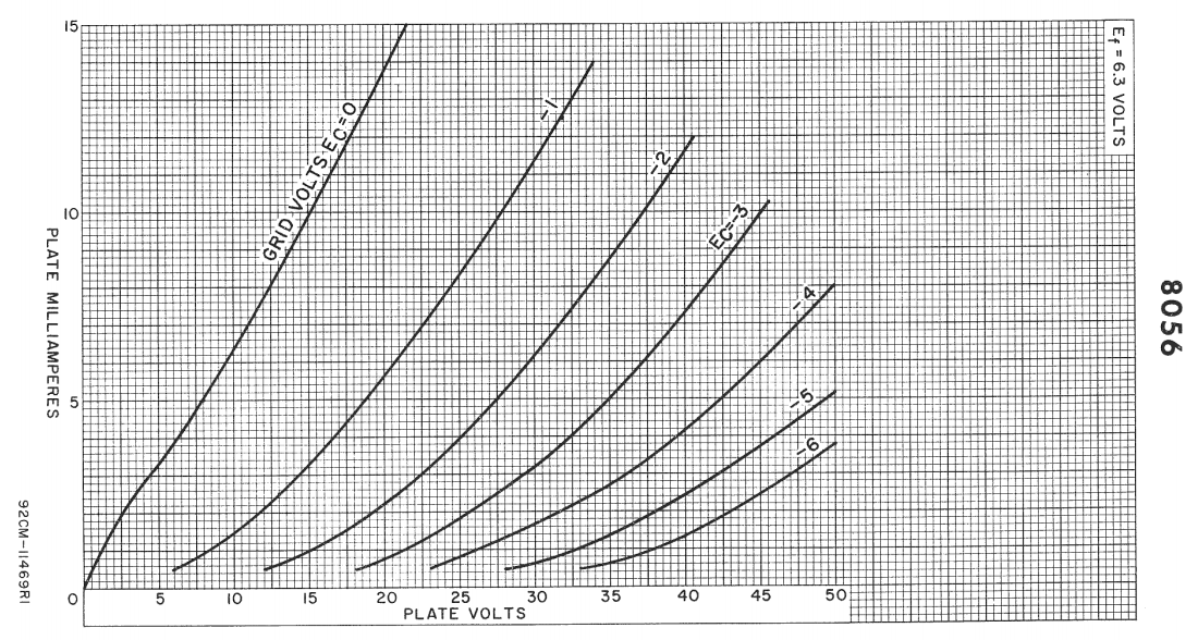
With a modest Mu, low plate resistance, and very low B+, it’s no wonder Bob decided to marry this interesting tube to a solid state partner for his Blender. The 8056 heater requires 6.3V at 135mA. At this voltage and heater requirement, it’s close to being practical for modern portable devices. In their heyday Nuvistors were used in battery-powered and efficiency-critical applications like the US Space Program and military radios and communications equipment.
Would I ever build something with Nuvistors? It’s tough to say. I’ve been on a casual hunt for tubes that might be suitable in a portable battery-powered application. Other candidates are the Korg Nutube or the sub-mini 6088. Like all things in this hobby, there are trade-offs. The Nuvistor 8056 heaters are hungry relative to these other options, but the other characteristics are very attractive. In all likelihood, I’ll try them all eventually. This is why I DIY.
Top 10 tips for PCBs on EasyEDA
I’m a believer in point-to-point construction, but not because I think it necessarily sounds any better. Point-to-point is simply the quickest and easiest way to try a new circuit. With tubes, high voltage caps, and through hole resistors, building without boards is straightforward (once you have some understanding of properly grounding circuits). When incorporating TO92, TO220, heatsinks, etc, a PCB starts to look much more appealing.
If you’ve been following my adventures, you’ve seen that I’ve been experimenting with PCBs recently. Most of my schematics are drawn in EasyEDA. EasyEDA is part of the JLCPCB family, where you can quickly import and order boards (you can also export Gerber files for purchasing elsewhere). Based on my experience so far, and the advice of a cool dude name Matt, here are some thoughts and tips for working with EasyEDA/JLCPCB:
- Take advantage of the grid/snap spacing for layouts: I set my grid to 125mil (1/8″), the snap to 31.25mil (1/32″), and the alt snap to 12.5mil.

- Create m3/4-40 mounting holes: I make my holes 125mil (1/8″)
- Make all connections on one side of the board (where possible)
- Use the reverse side as a ground plane
- Don’t be shy about creating your own parts (this is the PCB Lib function)!
- Don’t use standard TO92 packages; use TO92 ammo package footprints

- Enlarge holes for wire-to-board connections and make the pads generous where you can
- My preference is to keep tube sockets off boards to prevent footprint issues, board flexing, and keep heater wiring flexible
- Avoid parallel tracks for anything carrying AC (signal or power): see Doug Self for good reading on coupling
- Add multiple hole connections for film caps (options for multiple radial and axial types)

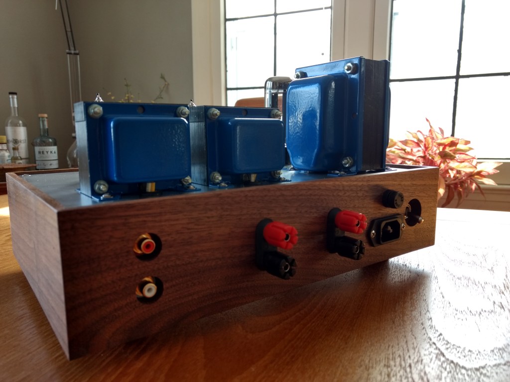
April/May has been a whirlwind in the WTF Amps household, but we should be returning to actual building soon. I’ve got about 30lbs of transformers and aluminum plates impatiently waiting for some actual hobby time to shake out of my schedule. Big boy mono blocks.
Tube news? Gibson files chapter 11
Gibson, the largest US-based company in the musical instruments business, is having a come to Jesus moment. After its early 2010’s binge on A/V properties (KRK, Stanton, Cerwin Vega, Onkyo, TEAC, etc) and subsequently ballooning debt, Gibson never really seemed to dig in with a new strategic direction to leverage the diversified catalog. It just doubled down with the Guitar Centers of the world (who is also not looking too hot these days). One has to wonder exactly what the strategic play was. In any case, several product/line missteps and steadily declining revenue from 2014 onward has brought us here.
As someone working in the MI industry, it’s difficult to resist the urge to wax poetic about Gibson having lost its way. Whether it was a miscalculated pump and dump deal or Juszkiewicz spending too much time in the varnish room, there’s a silver lining. Gibson has vowed to re-focus its efforts on guitars (and maybe amps). In an economic environment as interconnected and multipolar as today’s, that’s probably the right solution.
So I’m taking bets on whether Gibson will be relaunching their amplifier line. Here’s a great selection of schematics. We’ve seen PRS making similar moves to complement their guitar line in recent years. Will we see a new Skylark from Gibson?
Muchedumbre XL PSU details


These two buffers are very similar. In fact, the XL came about as a simple mutation of the regular version when the cost/size of an extra tube was not an issue and there was the possibility of driving a lower impedance load (long cables, solid state amps, etc). In theory, the power supply requirements are identical down to the B+ current draw. “In theory.” Although if you study the schematics carefully and read the write ups, you’ll see that my steel-trap mind is missing a spring or two.
The original Muchedumbre called for a Triad C-3X (500 ohm DCR). On the schematic for the XL, I seem to have spec’d the Traid C-7X (270 ohm DCR). The inductance rating for these two chokes is identical, but the C-7X has about half the DCR. Is that going to be a problem? In short: no. I love tubes; they make up for all my shortcomings.
Current draw between the two configurations (XL vs vanilla) is the same on paper, despite the extra triodes in the XL (the added triodes are in series, so the same current flows through both). If using the same choke, the B+ should end up the same. With the modest current in the pre, however, you have plenty of leeway in DCR before you have to worry about big B+ changes.
ΔVdchoke = (500 ohms – 270 ohms) * (10mA x 2) = 4.6V
No problemo.
Say you have a big old Hammond 193M at 10H and 63 ohms DCR. You could very safely use that, too. The lower DCR gives you a little more room in the B+ to increase the series/sense resistor if you’re amps’s input impedance suggests it. You gain some B+ in the choke DCR and drop it back down across the sense resistor. Current across the DCR is twice that of each channel, so assuming 10mA bias per channel:
ΔVdchoke = (500 ohm spec – 63 ohm part) * (10mA bias x 2 channels) = +8.75V
ΔVdsense = (1k5 ohm spec – 3k ohm part) * 10mA bias = -15V
Net result is a 6.25V deviation from the ‘on paper’ spec’d parts. That’s less than 5% of the B+, so better than parts tolerance in a lot of cases (e.g. low frequency chokes). The x-axis divisions on most tube datasheets are 20-25V, so they’re only so precise. Generally, 10% changes in B+ based on available part specs is probably about where I would return to my load lines to recalculate. In practice, I sometimes build anyways and then measure actual B+ before worrying about anything.
Solder and wire beats paper and pen.
New Project: El Mighty Cacahuate
The bones of a new project write-up are posted! This is for a ~2W EL84 SET amplifier. the amp is a modest project in cost and complexity, but I tried to make this write-up more in-depth than usual. Hopefully it’s a good glimpse into single-ended amps and general tube design for some aspiring hobbyists out there.
Click here for El Mighty Cacahuate
Class A FET power buffers
I’ve been kicking the hybrid amplifier can down the road for quite a while. In essence, I’m looking to do a bigger EL Estudiante. An amp capable of driving speakers to a dozen or two watts using a MOSFET follower output stage for current gain and a tube handling the voltage gain. While this is not especially difficult on paper, making something that is an interesting and practical alternative to tube output stages is not necessarily so straightforward.
On one hand, one should consider the target user. Most tube enthusiasts do not need so much power, so we can bias in Class A and avoid a whole lot of AB headaches and worry about bias adjustment, crossover distortion, etc. This has to be balanced against heatsinking and thermal considerations, of course. Coming from the world of tubes, our audiophile anti-bodies have already pretty well encysted any commonsensical tendencies we may once have harbored, but the smoke point of drywall hasn’t changed. That is to say solid state does not magically make Class A cool, efficient, or pragmatic, but why make something hotter, more wasteful, and more burdensome than vacuum tech? We’re hoping to make something that is more than the sum of its parts.
The Aikido Hybrid 16W SE by John Broskie has about as much power as most probably need. Sixteen is two to the fourth watts, so four times three decibels per doubling of power for a 12db increase over nominal speaker rating (eg your 90db speakers peak at 102db). The quiescent current is a very serious 2A. It is a single-ended MOSFET source-follower loaded by a current source. There’s little not to like other than the coupling caps (contrast this with output transformers for AC coupling in full tube amps). See also Rod Elliott and Pavel Macura’s CCS-loaded follower here.

We can make single-ended more efficient with an inductive load. Just like a choke load with tubes (eg Luciernaga), an inductive load on a MOSFET lets it swing voltage past the power rails. The MoFo is an example of a single-ended source-follower MOSFET with a simple passive choke load (50-150mH and very low DCR). This is much more efficient than an active CCS in an absolute watts dissipated sense (note the much lower supply voltage), but chokes ain’t cheap and you still need a good dose of current.

If you want to lower the quiescent current needed, but stay in Class A, push-pull source-followers are the way to go. Papa Pass’s F4 power buffer does exactly this to cut the quiescent current needed in half. The need to match FETs may be unappealing, but compared to his single-ended F3, F2, or Aleph J, the power delivery into 4 ohm loads is much improved. Note Broskie suggests the same push-pull MOSFET approach (with a different biasing scheme) in the Moskido amp design.
Any of the above would probably sound pretty good: like a tube feeding a very transparent solid state amp. If the amount of power you need is modest (and it probably is if you’re a tube enthusiast), these approaches have made very nice speaker amps. Hopefully I’ll have my own design to contribute soon. MOSFET followers would also make a great multi-watt amp for low sensitivity and low impedance headphones, like the HIFIMAN HE-6.
The HE-6 are rated at a sensitivity of 83.5db at 1 mW. With 1000x more power (1W), we’d make 103.5db (a 20db increase). Around 5W input makes it a cool 110db. Coincidentally, this is the power rating of the amp HIFIMAN recommends as a pairing. The HE-6’s 50 ohm impedance lowers the quiescent current needed in a MOSFET output stage, though still requires a voltage rail high enough to prevent clipping. A quick approximation for voltage would be:
power = Vrms² / impedance
5W x 50 ohms = 16 Vrms²
16 Vrms x √2 x 2 = 46 Vptp
So about a 48V power rail (or +/- 24V) gets us in the neighborhood. Doing the same for current:
power = Irms² x impedance
5W / 50 ohms = 0.32 Irms²
0.32 Irms x √2 = 0.5 Ipeak
We only need about a 48V power rail and 0.5A quiescent current per channel to get us 5W into a 50 ohm load if using a CCS loaded MOSFET. If we choke load, cut the 48V in half. If we use Class A push pull, cut the current in half. The heatsinks aren’t going to be tiny, but a desktop size amp isn’t out of the question.
The difference between a headphone amp and a preamp
This is a question that, as a beginner builder, confused me quite a bit. While it isn’t too hard to understand why a preamp cannot drive power-hungry low-impedance headphones, it’s less obvious what separates an amp that can drive headphones from a low gain line stage. Headphone amps and preamps often share the same small signal tubes, usually Class A, and often single-ended.
Here are the modifications I would make to the El Estudiante headphone amp to make it better suited to line stage duty. While a purposely designed line stage might perform better, I can’t think of a way to do a halfway decent tube line stage any cheaper or simpler. If you don’t go mad on caps, this costs less than the headphone version.
Output Stage
Power requires both voltage and current. How much voltage or current required for a given amount of power depends on the load you intend to drive. Remember:
Power = Voltage x Current
But also:
Power = Voltage² / Impedance
AND
Power = Current² x Impedance
To create power into low impedance headphones, we need current. This drives a lot of design decisions in tube headphone amplifiers. Common approaches to create power are push-pull output stages (eg SRPP, White Cathode Follower), output transformers, and solid state power buffering. The Estudiante creates the power required for low impedance headphones using the latter approach: a single-ended CCS-loaded MOSFET buffer. At a 100mA quiescent current, it can make about 150mW into 32 ohms:
0.1A² x 32 ohms x 1/2 = 150mW
(note RMS = Peak / √2)
On the other hand, with a 10,000 ohm input impedance on an amplifier, this current is unnecessary because the maximum ‘power’ is limited by the voltage, not the current:
24V² / (10,000 ohms x 2) = 25 mW
Now we don’t really look at power output per se in line stages and we’re rounding up the peak output voltage as half the power rail voltage, but it’s obvious that we don’t need all the current to drive the input impedance of an amplifier because we’re limited by voltage anyways. Consequently, we can lower the current in the MOSFET output stage to something that doesn’t even require a heatsink, making a preamp build that much simpler and cheaper.
With the LM317 CCS, we calculate the needed set resistor as 1.25V / Iq (where Iq is the idle current). A resistor of 100 ohms will give us 12.5mA idle current, which should be plenty for a reasonably low output impedance, but not enough to need a heatsink (I would probably still bolt my TO220 parts to the chassis though).
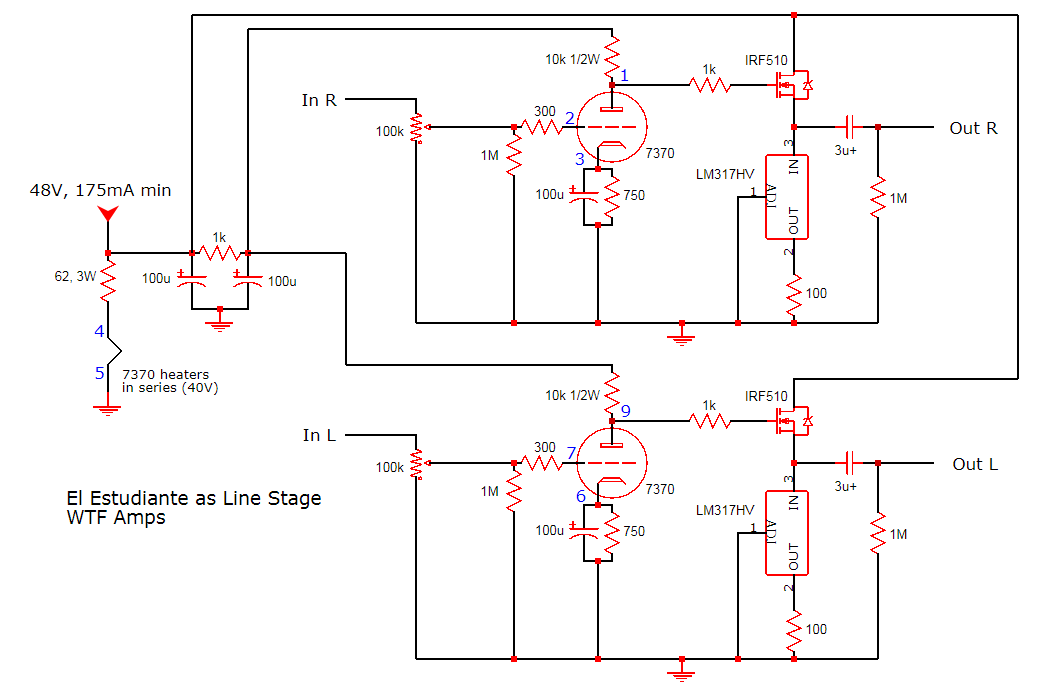
In addition to lowering the idle current in the MOSFETs, we can change the big nasty electrolytic cap found in the headphone amplifier to a higher quality film cap. Electrolytics are great where you need a large capacitance in a small and affordable package, like the output coupling cap in a headphone amplifier, but electrolytic capacitors have been shown to create distortion at low frequencies (see Douglas Self’s Small Signal Audio Design) and exhibit leakage current that creates a thump on power down (which may just be annoying on headphones, but potentially damaging on a high power speaker amplifier).
For an input impedance of 10,000 ohms and a -3db point of 5 hertz, Our new cap size in microfarads (uF) is calculated as:
1,000,000 / (2 x Pi x 10,000 ohms x 5 hz) = ~ 3uF
A film cap of this size at a rating of only 63V+ is not hard to come by. I’d probably buy an assortment just to see if I could hear a difference. We should also increase the size of the loading resistor on the output from the 1k in the headphone amplifier to something like 100k or 1M so that we aren’t rolling off the bass or unnecessarily loading down the MOSFET output stage.
Finally, because we’re reducing the current in the output stage, our power supply requirement is relaxed, maybe opening up more wall-wart options to power the project. So if you’re looking for a simple, low-voltage, and cheap tube preamp option, modifying a headphone amplifier like the El Estudiante may be a good option. I’ve even used the headphone amp to feed power amplifiers in a pinch and it sounds surprisingly good.
