If you’ve missed the recent hubbub, Schitt is launching a line of drink coasters. It just so happens that these coasters double as unsupported DIY projects with scarce documentation.
The schematic shows a 6418 sub-miniature triode direct connected to an AB push-pull transistor output stage (cap coupled). Power is a blistering 30V to the tube and 15V to the output stage, cleverly derived with a bridge doubler and regulated with LM317s.
Schitt is hedging the product with extra coy advertising (AKA the Schitt Shtick) and reinforcing in several places that they are not a DIY company. Hence the product is a coaster, not a miniature hybrid amplifier. It will come at no surprise to Schitt when DIY documentation is created by early adopter hobbyist communities, I’m sure.
Some of the quoted specs:
Frequency Response: not terrible, but not exciting (like 10-100K, -1dB or so)
Power Output: much less than anything else we make (like, less than Fulla 2, maybe 400mW into 32 ohms, all in, 10% THD or so)
THD: about 0.5% at 1V RMS (6418 tubes) or about 1.5% at 1V RMS (6088 tubes)
IMD: didn’t bother measuring, this amp ain’t about measurement
Output Impedance: about 8 ohms (yes, 8, not 0.8, not 0.08), in case you didn’t get the memo, this ain’t a high-performance amp
What is it about Schitt’s non-committal and self-effacing copy that gets so many people so excited? Why did I just buy a small lot of 6418s? Why are coasters already on the way to me?
Phono preamps can be tricky builds due to the need for high gain with low noise. In tube land, linear high gain is not too difficult to achieve even without feedback. Power-supply-based noise can often be brute forced with extra filtering, actively regulated B+, and/or DC-powered tube heaters. High PSRR topologies (eg differential) also have an advantage in the early amplification stages.
building phono PSUs be like
The place where most DIY builders are probably tripped up is the mysterious RIAA voodoo. Because the physical limitations of the vinyl medium and cutting process require a limiting of low frequencies and a boosting of high frequencies, we need to reverse this EQ on the playback end in order to get back to ‘flat’ frequency response.
At it’s most basic, the RIAA equalization standard defines three frequencies: 50hz, 500hz, and 2122hz. We should have a 20db boost to 50hz, a -20db/decade transition from 50hz to 500hz, flat playback from 500hz to 2122hz, and a -20db/decade falling response above 2122hz. Note that 20db/decade is equivalent to 6db/octave, so these are not especially steep filters.
Splitting the RIAA requirements between low (<1khz) and high (>1khz), the low frequency manipulation requires at least 20db of gain from whatever device we are using. This type of EQ is commonly referred to as a shelving filter. The high frequency portion is only reducing the response and so it doesn’t require gain (ignoring the overall gain needed to get to line-level signals). This reducing of the high frequencies can be as simple as a first order low pass filter (just a resistor and a cap).
Tubes, with their fairly high output impedance and finite Mu, complicate RIAA frequency-dependent impedance calculations. Operational amplifiers, on the other hand, make filter maths fairly straight forward. Here’s an example:
Starting at the output, the R1 and C1 combination form a simple low pass filter. Because the output impedance of opamps is so low, our equation need only involve the cap and resistor:
Begin with a tight tolerance capacitor (say 0.1uF) and you’ll get a resistor value that may come off the shelf or be created with a parallel/series combination (in the case of a 0.1uF C1, the resistor would need to be 750 ohms). The resistor appears in series with the output, so large values may require a high input impedance in the following stage.
The shelving filter created by R2, C2, and R3 appears in the feedback circuit of the opamp. Because we need 20db of gain, we know that the ratio of R2 to R3 should be approximately 10:1 (a 10x voltage gain difference corresponds to 20db). The 50hz point is set by the combination of R2 and C2 and is found with the same kind of capacitor reactance equation as the low pass:
R2 = 1,000,000 / (2 * Pi * 50hz * C2)
Again, start with the cap value because caps have fewer options and are harder to find in a tight tolerance. A 0.047uF cap gives an R2 of about 68k, meaning R3 should be about 6K8. The overall gain of the stage is further set by R-gain (Av = 1 + R3/R-gain).
So that’s a pretty simple way to EQ your vinyl to flat. More gain to bring the signal up to line level could be added by following the EQ/opamp stage with a ‘normal’ tube stage or two. Expect to see some more on this topic in a future project!
I’ve been kicking the hybrid amplifier can down the road for quite a while. In essence, I’m looking to do a bigger EL Estudiante. An amp capable of driving speakers to a dozen or two watts using a MOSFET follower output stage for current gain and a tube handling the voltage gain. While this is not especially difficult on paper, making something that is an interesting and practical alternative to tube output stages is not necessarily so straightforward.
On one hand, one should consider the target user. Most tube enthusiasts do not need so much power, so we can bias in Class A and avoid a whole lot of AB headaches and worry about bias adjustment, crossover distortion, etc. This has to be balanced against heatsinking and thermal considerations, of course. Coming from the world of tubes, our audiophile anti-bodies have already pretty well encysted any commonsensical tendencies we may once have harbored, but the smoke point of drywall hasn’t changed. That is to say solid state does not magically make Class A cool, efficient, or pragmatic, but why make something hotter, more wasteful, and more burdensome than vacuum tech? We’re hoping to make something that is more than the sum of its parts.
The Aikido Hybrid 16W SE by John Broskie has about as much power as most probably need. Sixteen is two to the fourth watts, so four times three decibels per doubling of power for a 12db increase over nominal speaker rating (eg your 90db speakers peak at 102db). The quiescent current is a very serious 2A. It is a single-ended MOSFET source-follower loaded by a current source. There’s little not to like other than the coupling caps (contrast this with output transformers for AC coupling in full tube amps). See also Rod Elliott and Pavel Macura’s CCS-loaded follower here.
We can make single-ended more efficient with an inductive load. Just like a choke load with tubes (eg Luciernaga), an inductive load on a MOSFET lets it swing voltage past the power rails. The MoFo is an example of a single-ended source-follower MOSFET with a simple passive choke load (50-150mH and very low DCR). This is much more efficient than an active CCS in an absolute watts dissipated sense (note the much lower supply voltage), but chokes ain’t cheap and you still need a good dose of current.
If you want to lower the quiescent current needed, but stay in Class A, push-pull source-followers are the way to go. Papa Pass’s F4 power buffer does exactly this to cut the quiescent current needed in half. The need to match FETs may be unappealing, but compared to his single-ended F3, F2, or Aleph J, the power delivery into 4 ohm loads is much improved. Note Broskie suggests the same push-pull MOSFET approach (with a different biasing scheme) in the Moskido amp design.
Any of the above would probably sound pretty good: like a tube feeding a very transparent solid state amp. If the amount of power you need is modest (and it probably is if you’re a tube enthusiast), these approaches have made very nice speaker amps. Hopefully I’ll have my own design to contribute soon. MOSFET followers would also make a great multi-watt amp for low sensitivity and low impedance headphones, like the HIFIMAN HE-6.
The HE-6 are rated at a sensitivity of 83.5db at 1 mW. With 1000x more power (1W), we’d make 103.5db (a 20db increase). Around 5W input makes it a cool 110db. Coincidentally, this is the power rating of the amp HIFIMAN recommends as a pairing. The HE-6’s 50 ohm impedance lowers the quiescent current needed in a MOSFET output stage, though still requires a voltage rail high enough to prevent clipping. A quick approximation for voltage would be:
power = Vrms² / impedance
5W x 50 ohms = 16 Vrms²
16 Vrms x √2 x 2 = 46 Vptp
So about a 48V power rail (or +/- 24V) gets us in the neighborhood. Doing the same for current:
power = Irms² x impedance
5W / 50 ohms = 0.32 Irms²
0.32 Irms x √2 = 0.5 Ipeak
We only need about a 48V power rail and 0.5A quiescent current per channel to get us 5W into a 50 ohm load if using a CCS loaded MOSFET. If we choke load, cut the 48V in half. If we use Class A push pull, cut the current in half. The heatsinks aren’t going to be tiny, but a desktop size amp isn’t out of the question.
All books on audio design that stoop to cover the archaic and backwards idea of vacuum tube amplification begrudgingly admit tubes are wonderful open-loop voltage amplification devices. They’re very linear (much more so than transistors without feedback), tolerant of high voltage, and forgiving of approximated parts values. Tubes do not make great current gain devices though. Therein lies the problem for us glow bulb fanatics. To make power, we need both voltage and current. We usually side-step the current-handling weakness of tubes by developing large voltage signals with multiple stages and then using an output transformer to turn the big voltage at modest current into modest voltage at big current.
Let’s look at an example.
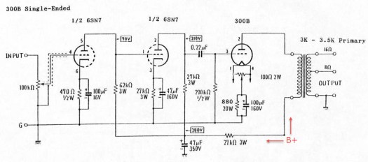
A somewhat classic single-ended triode uses two halves of a 6SN7 and a 300B in cascaded stages followed by a 3.5k to 8 ohm output transformer:
We know that the voltage gain of a grounded cathode with a bypassed cathode resistor is the Mu multiplied by the plate load divided by the sum of the plate load and the plate resistance. Accordingly, the amp above develops voltage gain of about 18x in the first stage, 16x in the second stage, and 3.2x in the final stage. This is an overall voltage gain of about 900x, meaning a 1V signal at the input becomes a 900V signal at the output. In reality, the 300B runs into grid or current cutoff before it gets anywhere near that much voltage swing at its plate and a more likely figure is about half this or 450V peak to peak.
This 450V peak to peak is still quite a lot of voltage. If you could directly drive an 8 ohm load with it [narrator: you can’t] you’d produce thousands of watts. To produce the thousands of watts, you’d use dozens of amps. You have about 0.06 amps [sad trombone]. We use an output transformer to step down the voltage and step up the current. We know that the voltage ratio of an output transformer is the square root of the impedance ratio. In the case of a 3.5k to 8 ohm transformer, that is the square root of 3,500/8 or about 21. Divide 450V by 21 and we get the voltage swing that the 8 ohm speaker is seeing. It’s about 22V peak to peak (seven and a half watts).
We created a hell of a lot of voltage just to step it down to a measly 22V peak to peak. This is where hybrids might come in. Solid state is quite happy driving amps of current into an 8 ohm load and only need a supply voltage of a couple dozen volts. They do away with the multiple voltage gain stages and output transformer. If you can create 22V of signal with a single tube stage, a transistor doesn’t need to make it any bigger; it just needs to provide enough current to drive a low impedance load like a speaker or headphone. Let the tube do what it does best (voltage gain) and let the transistor do what it does best (source lots of current).
So why don’t we see more hybrid designs? For one thing, the power supplies get complicated. You often want a bipolar (plus and minus) supply for the solid state section, a low voltage heater supply, and a high voltage supply for the tube’s plate. Although you rid yourself of an output transformer, you probably added a power transformer (and rectification, filter, etc). Another reason we don’t see more hybrid designs is that many designs which do exist don’t use the devices to their strengths and so cast doubt on the concept. When you see a single tube in an integrated amp, it’s often there as a simple cathode follower. I’ve got nothing against cathode followers, but that implementation is about as much a hybrid design as a burger with lettuce and tomato is a salad.
But by far the most likely reason we don’t see more hybrids (in my opinion) is that devotees of the objective/subjective, transistor/tube, modern/traditional design school are too human. If modern politics hasn’t sufficiently convinced you, the state of the audio market should. We’re kind of a bunch of tribal-minded, technocentric, get-off-my-lawn jerks. If you build a hybrid, you piss off both sides.
So yeah. Screw that. This was the long way of saying I’m building a hybrid amp.